Amp4 - Satellites
Design considerations
First, in order to minimize the cabling mess and eliminate the need for a separate enclosure for the electronics, I chose to put everything in the speaker cabinets. This does mean having to run longer line-level cables than is ideal for noise pickup, but the distance should be small enough to be acceptable at about 5m maximum, and it reduces the length of the speaker cables to practically nothing. Integrating everything has the advantage that the power supplies for each channel are separated, removing all the grounding problems I have had implementing multi-channel amps in one case, although I will have to be careful of loops via the interconnects and earth.
Small overall size implies small speaker drivers. Here lies a dilemma. I could either choose to have 5 medium sized speakers, each capable of reproducing the entire desired bandwidth, or I could have 5 small speakers plus a subwoofer. I went for the subwoofer as it makes placement much easier and I will be able to keep the same bandwidth I had with my previous speakers more easily, at the expense of stereo imaging.
Since they are so simple to construct and work so well, I will be using IC amplifiers again. Generally it will be very similar to amp 3. In keeping with my general desire for modularity, the crossover and amplifiers will have their own PCBs instead of being on one PCB as I did before.
The source will be my computer, using the 5.1 analogue outputs from the onboard sound (I refer to this as a 'soundcard' from here on, for simplicity, even though it's not really a card). It gives pretty good quality sound for an integrated thing, but there is some noise on the analogue outputs, seemingly picked up from the fans. A little searching suggests that this is a common problem with that particular chip, so in order to eliminate it I would have to purchase a new soundcard, ideally one which can encode to Dolby Digital on-the-fly and an external decoder to avoid analogue anywhere inside the noisy case (5.1 channel uncompressed digital output would be ideal, but there doesn't seem to be an easy way of accomplishing that). However the noise is quiet, so that's not a priority at the moment.
Speakers
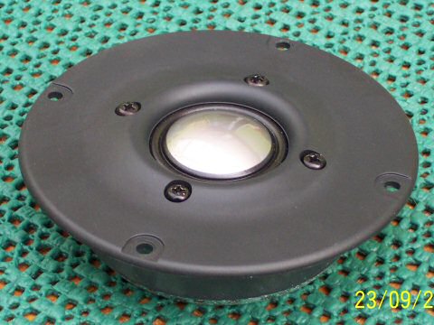
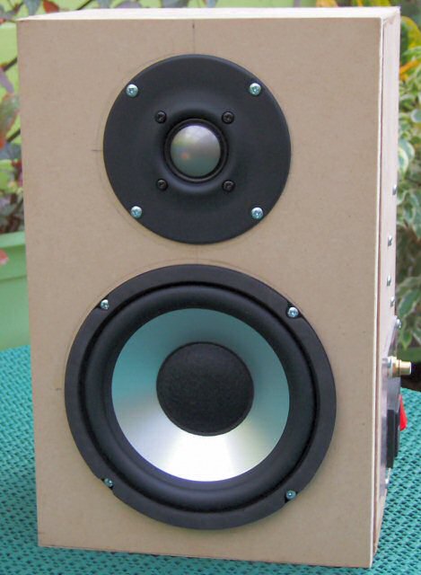
I hunted high and low for places that sell drivers in the UK. Since I last purchased any it seems that the number of retailers has dwindled. There are a few places that sell high-end stuff, but mostly beyond my price range since I need five of everything (that's the biggest compromise of a multi-channel setup over ordinary stereo). Eventually I found what I was looking for at CPC, in the form of the MCM 55-1860 6.5" aluminium cone woofer, and 53-530 titanium dome tweeter.
The woofer is absolutely superb. It is really quite inexpensive at about £12, but it looks to be of high quality. The magnet is of stupendous proportions for a small speaker, much of that size being the shielding (but it still can't be placed too close to my monitor without visible distortion). The cone, apart from looking all shiny and lovely, is very rigid, giving wide frequency response and theoretically low distortion , but of course no specifications are given for distortion. However, it does show a dip in response at around 2kHz (well before the cone starts breaking up) and so should really be crossed over quite low if a flat frequency response without EQ is desired.
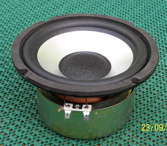
The tweeter is also very nice. With the highly visible titanium dome it is a reasonable aesthetic match to the woofer. Apart from that, I chose it because it has an unusually low resonant frequency of 880Hz, which is just barely low enough for a crossover frequency of 1.5kHz. The magnet is unshielded and quite strong, so I may have to make some shielding for the centre speaker, depending on how close to my monitors I need to place it, or change to LCD monitor(s).
The enclosure will have an internal volume of about 8 litres or so, which, after accounting for the volume taken up by all the stuff that needs to be packed inside, gives something close to a critically damped response (Q = 0.5) for nice smooth bass, easier matching to the subwoofer and sufficient room inside to fit all the electronics without headaches, while still being small enough to fit on a shelf, or wherever is convenient.
As a compromise between weight, ease of construction and rigidity, I chose 18mm MDF for the front baffle and 9mm MDF for all other panels.
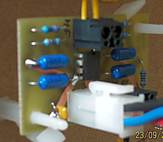
PSU
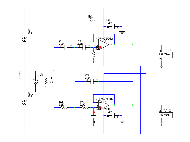
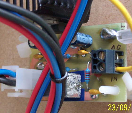
I wanted to do something a little different this time, so I went for a double bridge configuration with Shottky diodes to reduce diode losses and reduce noise. Schottky diodes of decent current/voltage rating are much more readily available and cheaper than they used to be, making them a good choice for this sort of application (Shottky diodes are good compared to junction diodes because they have lower forward voltage drop, giving better efficiency; and virtually no reverse recovery, which means low noise). Output is nominally 17V with a maximum current of 2A.
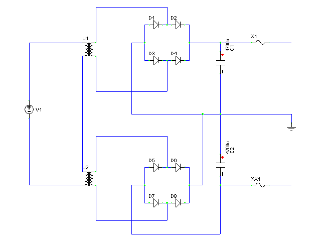
I've never been satisfied with using spade connectors for everything, even though they are cheap and reliable, so I purchased some Molex 4-way connectors, which seem to be identical to those used to connect ATX PSUs to motherboards, just smaller. This makes it much easier to connect everything together and it looks very neat, which I think justifies the cost.
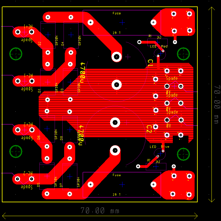
I left space for one more power connector in case I need to add anything else in the future. There is also some unfilled space for LEDs, which I can put in should I ever feel the need for more pretty lights.
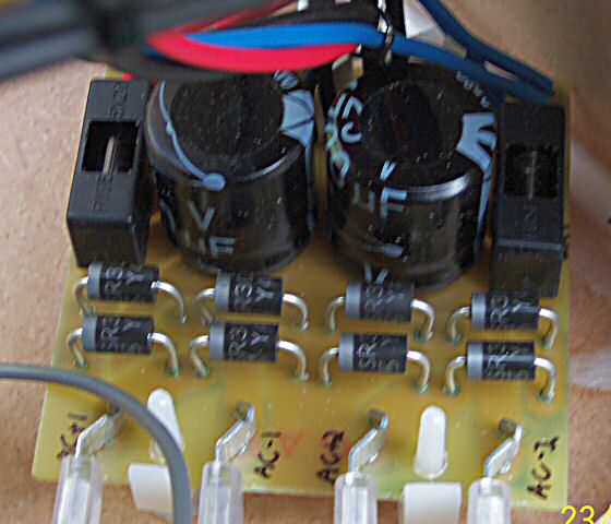
Crossover
Nothing special here. It's the same simple 2nd-order Bessel circuit I used in amp 3. Crossover frequency is 1.5kHz.
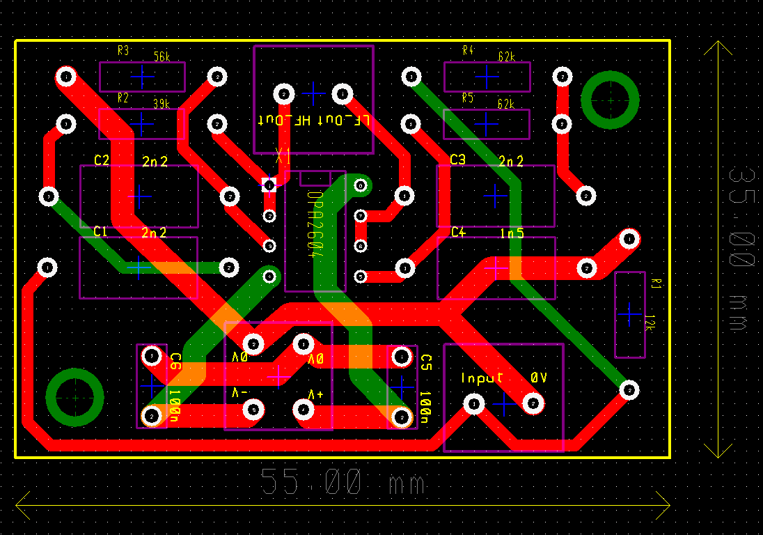
I used the same 1% metal film resistors and 1% polyester capacitors as before to keep tolerances tight without exorbitant cost.
Amplifiers
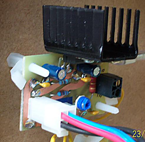
Again, virtually identical to the previous amplifiers I made. This time I used TDA2050s for both high and low frequency amps. I like the TD20x0 chips because they are have only 5 pins and are cheap.
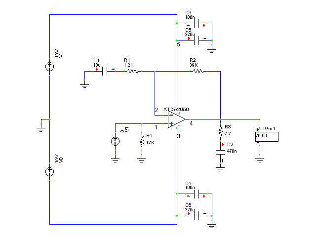
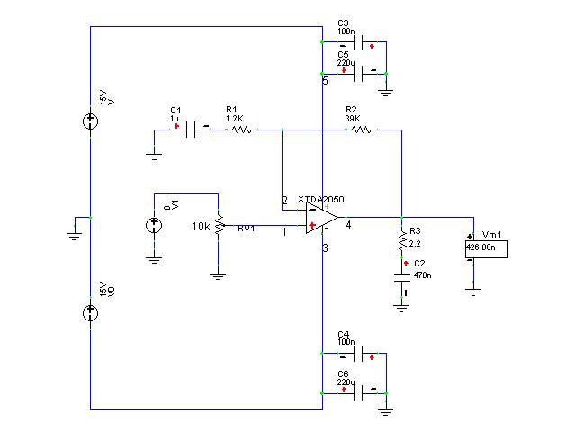
With a crossover frequency of 1.5kHz and bass below about 125Hz being directed to the subwoofer, power will be split more evenly than with the previous setup. Thus I didn't bother supplying the two amps with different voltages, which simplifies things a bit.
The only other change is from polypropylene to polyester for the DC feedback capacitors. I couldn't find the same ones I used before, which were particularly small for polypropylene due to low voltage rating of 63V, so I went with polyester instead, which are smaller and cheaper. Just as long as they're not electrolytic I don't mind what they are (electrolytic capacitors being probably the least reliable components in most circuits, and measurably non-linear too).
Building and testing
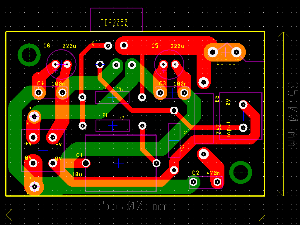
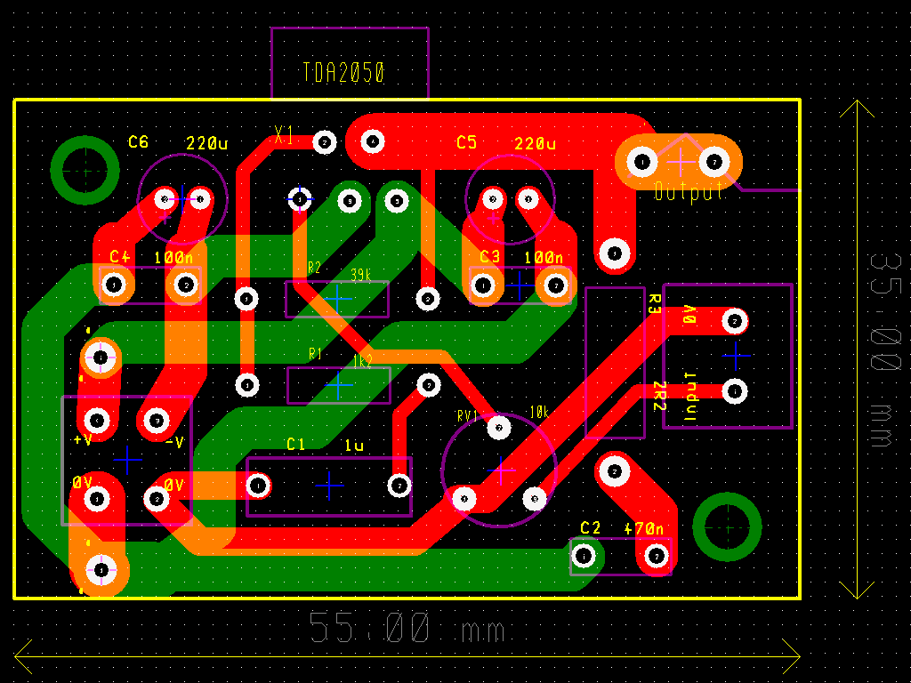
I still use the same construction process of printing the layout onto paper and using it as a guide to drill holes, then drawing the tracks manually with etch-resist pen, then etching with ferric-chloride. It's very cheap and easy to do double-sided boards that way. One small tip: I retained the leads from some components and used them to make vias.
I've said it before, but I'm very pleased with the Molex connectors I used for power. They make everything very neat and quick to assemble, which is helpful during the testing phase as everything is moved around a lot.
First the PSU was tested, then each of the three other boards (crossover, HF amp, LF amp) were tested individually to make sure I hadn't made any errors in the layout or during soldering (as if I could err!). Once that was done I connected it all together with a pair of old speakers (never test with expensive speakers first, in case of accidents). I verified that it all worked as expected, doing a few quick tests with an oscilloscope and multimeter, then connected the real speakers for some simple listening tests, again in case of gross errors. Everything being fine, I proceeded to construct a cabinet.
The joints between the 9mm panels are mitred to increase contact area. Mostly it's held together by glue, with a few screws at important points. There is a frame of 18mm batons around the back for screwing the back panel to (it needs to be removable to allow access to the electronics). The joints are all sealed with silicone sealant, except the rear panel, which I may make a foam gasket for.
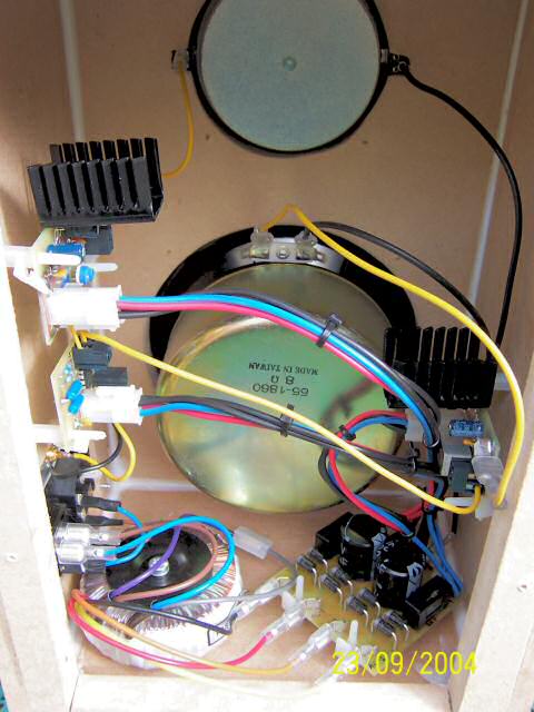
On fitting the components inside it seems I made a slight miscalculation, as it is all but impossible to connect wires to the ground spades on the PSU without first removing the woofer. I had wanted to make it possible to remove any single component independently, but I suppose it's not that important. Otherwise it all went according to plan.
As there is no particular way for heat to escape from inside (I wonder if the aluminium cone of the woofer is much better than normal materials for this?), I made sure to chose heatsinks large enough to keep the IC's junction temperature below the rated 150oC even with a high ambient temperature of 50oC, although I hope it never actually gets that hot inside! Even if the junction temperature were to become too high the chip will just shut itself down, so it should not be possible for them to be damaged thermally in any case.
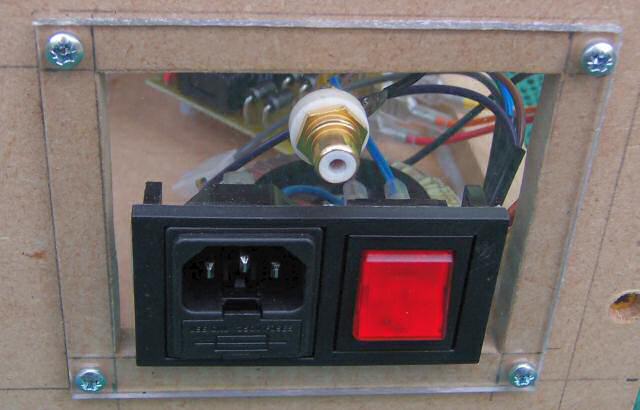
The external connectors are mounted on a small plastic panel, partly because it makes mounting easier, and partly because it allows easy changing of connectors, should I ever need to, e.g. if I wanted to change to a balanced input.
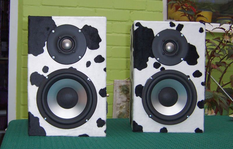
To finish them, I chose the ubiquitous cow-print fur-fabric. Not only does it look good (ok, a few seem to disagree about that, but they have no taste!), but it also helps reduce diffraction at high frequencies by attenuating them before they reach the edge of the baffle (I'm not sure how much benefit there is in practice, but it does seem to work subjectively).
Overall impressions and lessons learnt
There's only one of them at the moment, which obviously means I can't listen properly, but even listening to one I am very pleased. It sounds clean, with quite a lot of bass. This is rather surprising, as the -3dB frequency should be somewhere around 115Hz, and with the very low Q I would expect rather weak bass without the subwoofer. This is not a bad point however!
Perhaps the most important thing is that they look very smart. The metal diaphragms look high-tech and expensive, belying their modest cost. I think I'll have to get some LEDs to put in the spaces left in the PSU for that purpose, since the connector panel on the side is made of transparent plastic, begging to give a nice interior view.
On the down side, they are less efficient than my last speakers (the woofer is specified as being 88dB/W/m compared to about 94dB for my old speakers), but it's no problem to just turn up the volume a bit. More seriously, the tweeter's dome sticks out, so I have to be very careful to never lay the speakers face down or they will be damaged.
I will write more when there are more speakers to listen to. That could be some time; partly due to laziness, and partly because Farnell are still out of stock of the PCB terminals I ordered...
Update: I've now finished two out of the five, so proper stereo listening tests are possible. I also temporarily hooked up one channel of my old amp to the subwoofer channel to fill out the bass properly.
Stereo imaging is excellent. Sounds are well localized and they sound wider than my old speakers (presumably the small size of the baffle means more reverberant energy reaching my ears). With a subwoofer attached, albeit a temporary one, I can say I am quite satisfied with the bass. It's very tight, as expected from the low Q (the speaker used for the sub was tweaked slightly to have a Q of ~0.5 which is what I want to achieve ultimately), without being too weak. The low pass filter applied to the sub-out of my sound card just happens to integrate very well with the roll off of the satellite speakers, so that made things easy.
On the downside, the reduced high frequency output off-axis is very noticeable. If used as a plain old stereo pair then I might say that a super-tweeter would be a good idea, but with five of them and me in a fixed position it shouldn't be a problem.
Update: They're all finished! I was putting it off because it's so tedious to create five identical copies of everything. I couldn't be happier with the end results. Stereo imaging is, without wanting to sound like I'm exaggerating, truly awesome, with individual sounds being clearly positioned at specific points in space. The sound is very clean, which is likely due to the low distortion of rigid metal drivers, as expected.
I took some crude frequency response measurements to make sure that they didn't have any gross errors and to adjust the relative levels of the tweeters. It's just as well I did, because a huge dip at the crossover frequency of one of them alerted me to a reverse connected tweeter. Below you can see an FFT from one of the speakers:
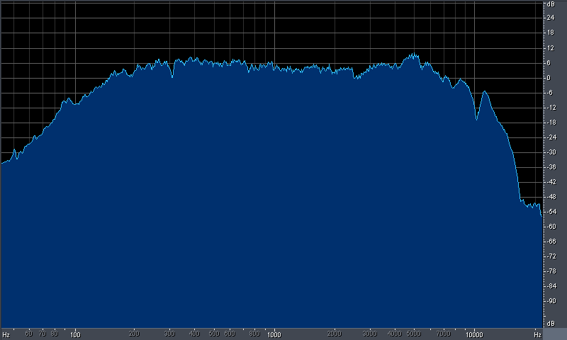
The accuracy is unknown, since the microphone is uncalibrated and I have no way of removing room interactions (oh, for an anechoic chamber of my own!). Still it shows that they are probably not too far from flat. The low end rolls off higher than predicted, but that is most likely from the microphone, since they don't sound like they start rolling off at 200Hz like that (update: it's baffle step. I deliberately didn't compensate for it in the electronics because the speakers are used flat against the wall, but the measurements were performed in the middle of the room). There is greatly reduced output above 10kHz and it's generally lumpy up there, maybe exacerbated by the microphone - no way of knowing for sure. No sign of peaks from woofer breakup, which suggests that the crossover frequency is low enough.
So that's it. Now I have to move on to creating the subwoofer. I have some ideas...