Coaxial Tower Speakers
After replacing the rear surround speakers in our living room, of course I wanted to replace the front speakers with nicer ones too. I built the old ones a very long time ago, when my woodworking skills were not good enough for me to want to put a photo of the old speakers here. I also recently replaced the TV stand with one made out of wood and aluminium extrusions, so I had the idea of trying to make some speakers in the same way. This would visually match the TV stand, and potentially allow the speakers to be assembled without any wood-to-wood joins at all, minimizing the amount of effort required from me. I've never seen any speakers made this way, so I had no idea if it was going to work well or not.
Drivers
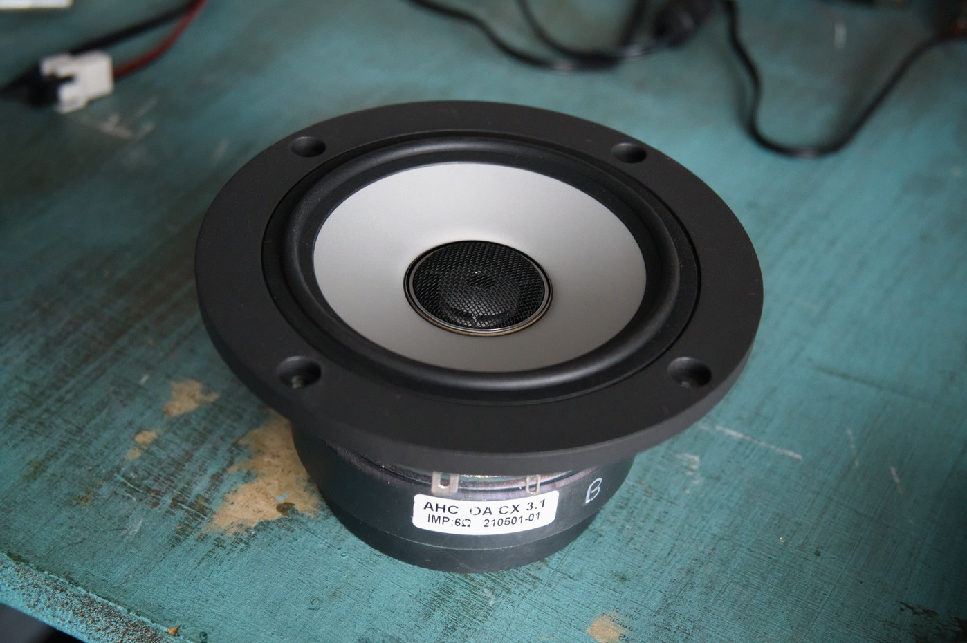
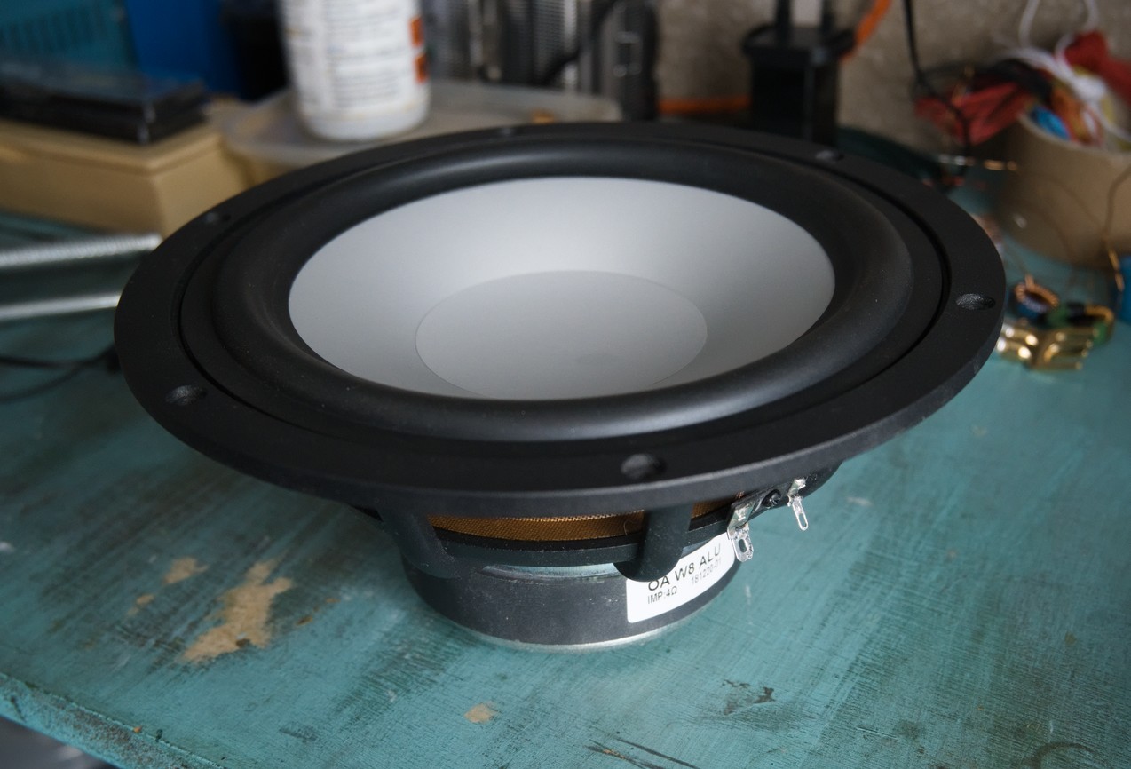
I wanted to use coaxial drivers again, as that has worked well for me before. It's hard to find good coaxial drivers that aren't expensive, and I didn't want to use the same ones that I used last time (just because I wanted to try something new, not because the ones I used before weren't good). Eventually I managed to find the CX 3.1, made by Omnes Audio that looked like it might be ok. They also make a variety of matching woofers, from which I chose to use the W8 Alu 4Ω 8" woofers, as using a pair of those with each coax driver would give reasonably matched sensitivity.
I measured the impedance of all the drivers to make sure they worked as specified, and to aid in crossover design. The results were all fine, and the woofers are very close to each other, which bodes well.


Enclosure
The woofers are best suited to vented enclosures, and with two woofers per channel the enclosures ended up needing to be rather large, at 100l in volume with a port 10cm in diameter and 15cm long to tune them to 33Hz. I started with a 2D CAD drawing of how that might look.
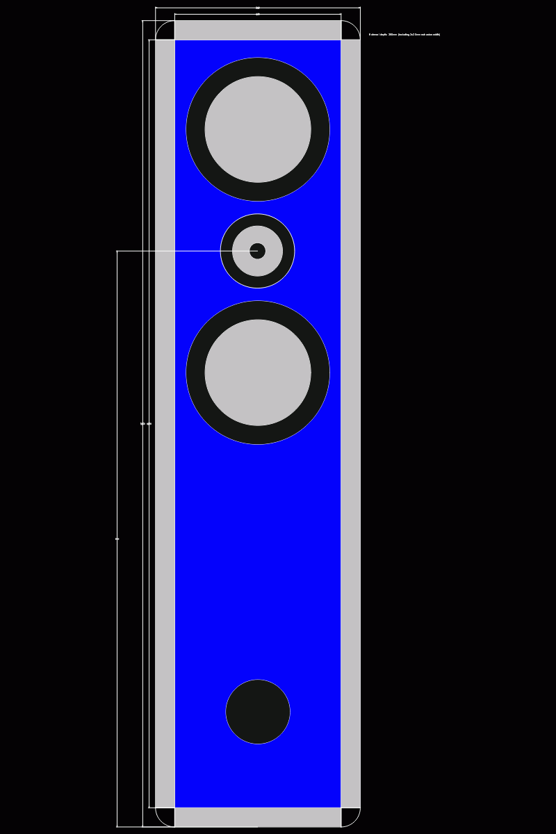
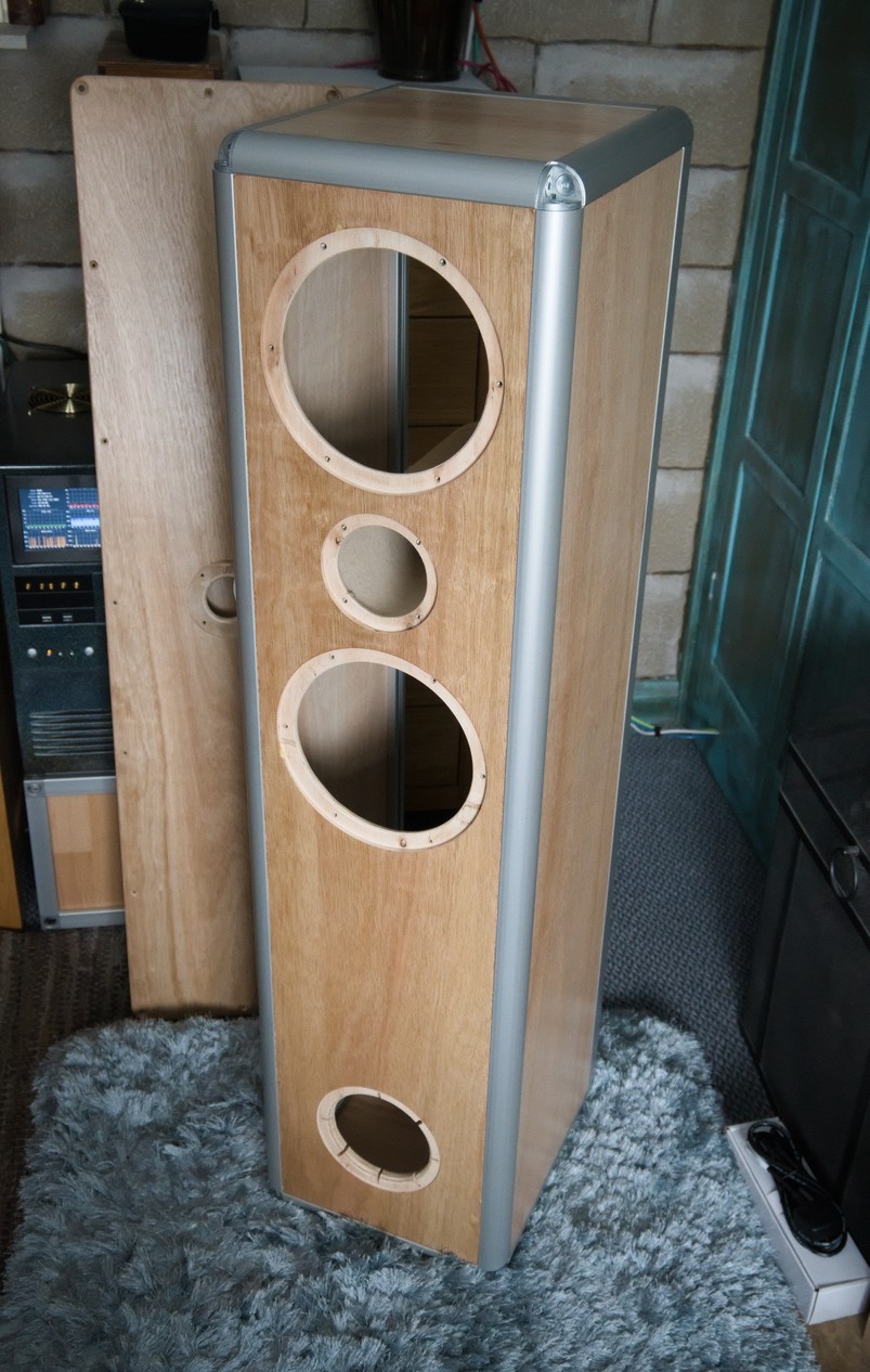
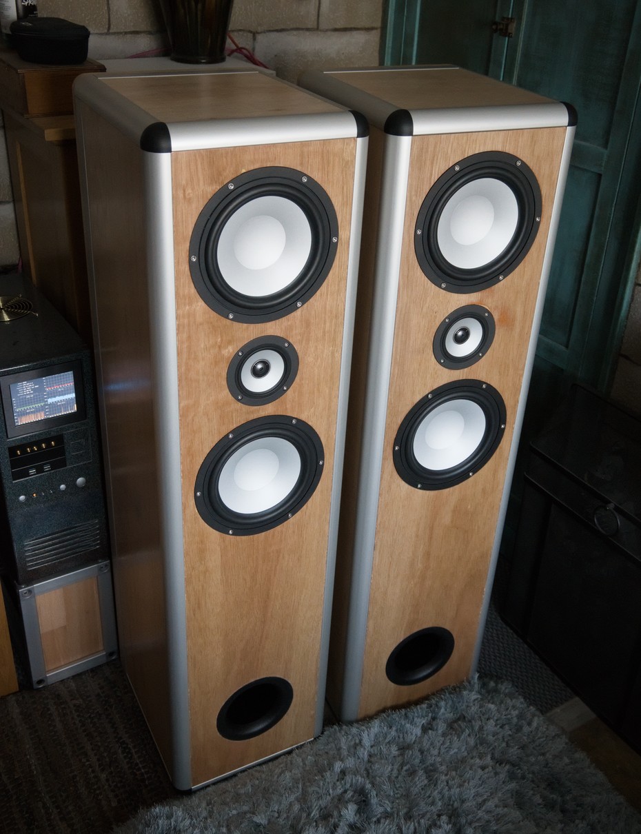
With the width and depth constrained by the amount of room beside the TV stand where the speakers would be positioned, they must be tall. This is actually helpful, as it allows the drivers to be placed high enough to be at ear level when we are seated watching the TV. I went with an MTM layout (not really the right name in this case - maybe they should be called WCW), mainly because I was told it looks better than the alternative TMM (and I agree).
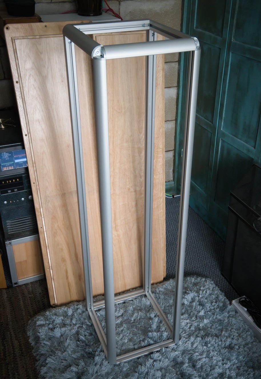
With the dimensions decided, I ordered some aluminium and some wood. Though I wanted to use solid oak to match the TV stand, it would have been too expensive, so I used plywood instead.
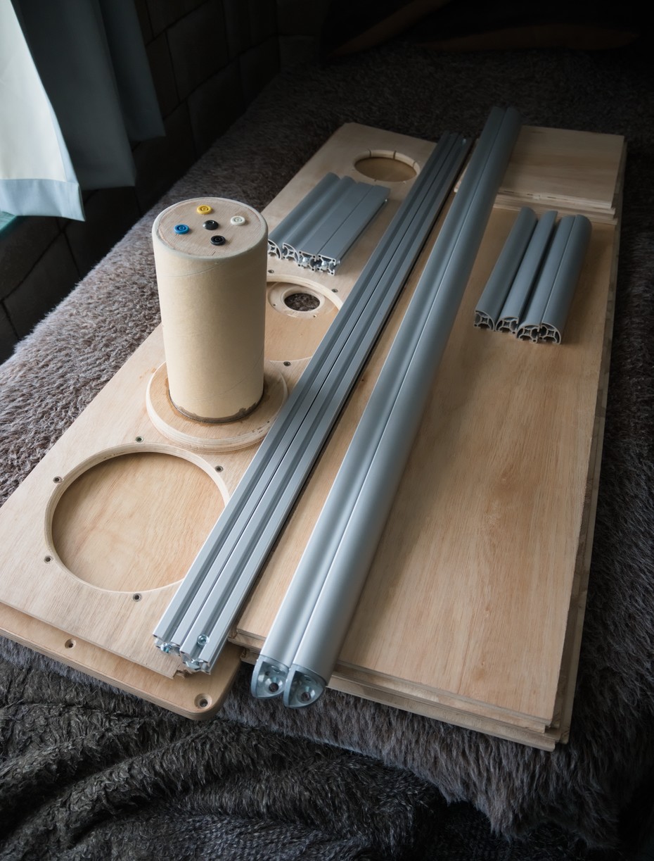
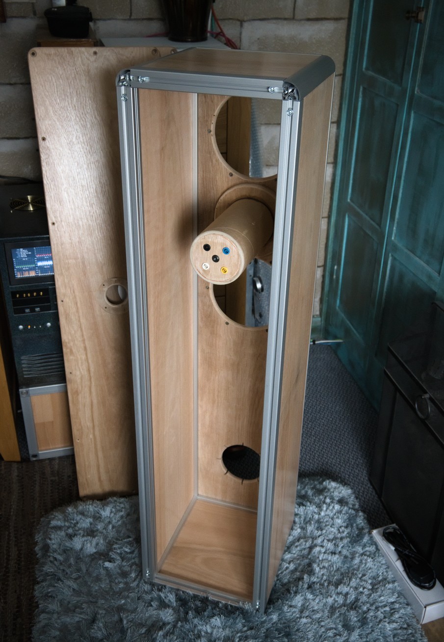
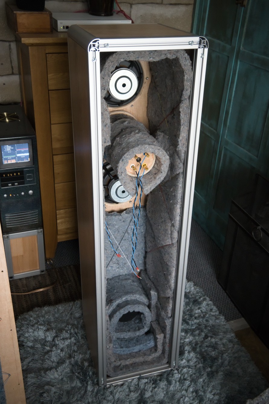
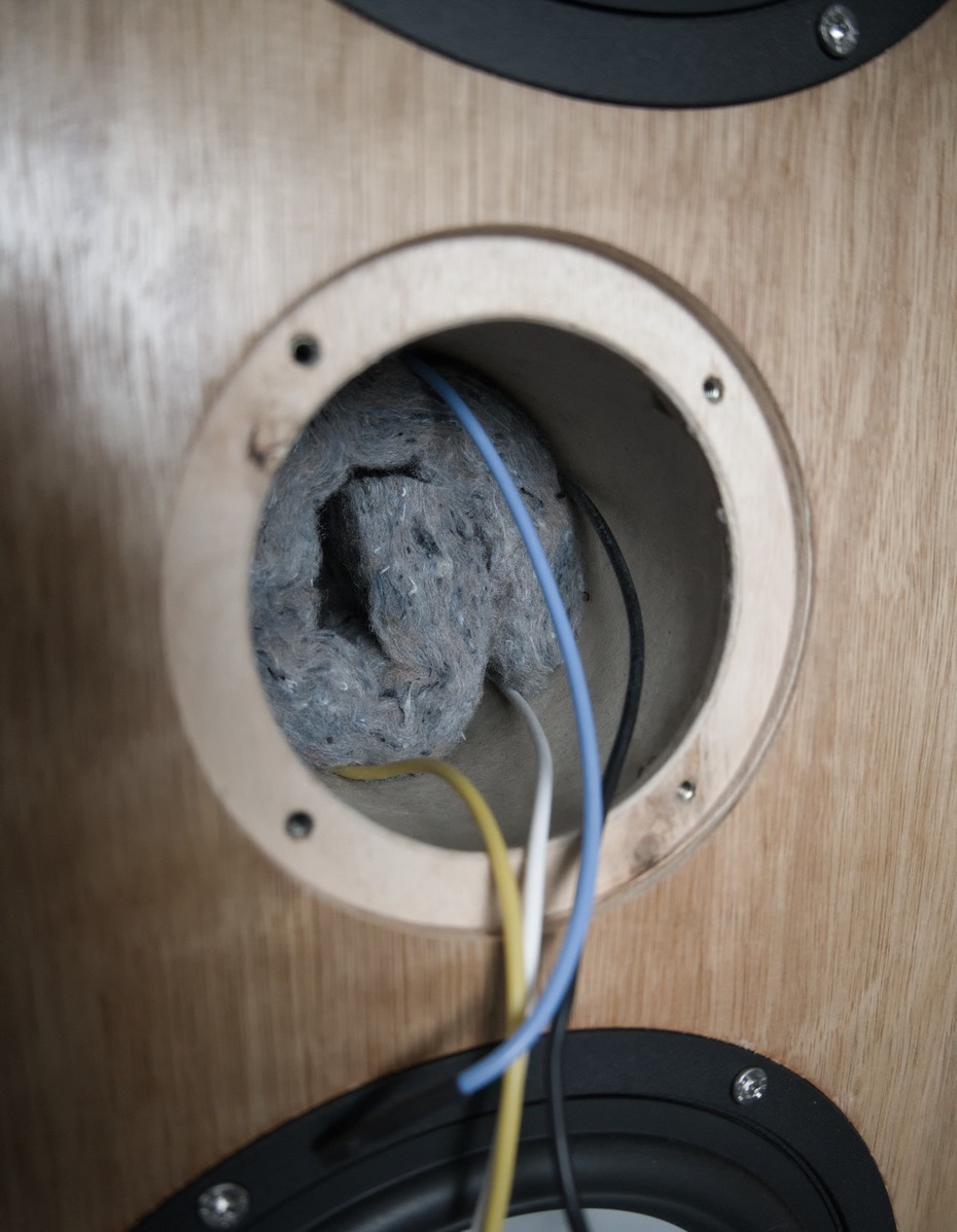
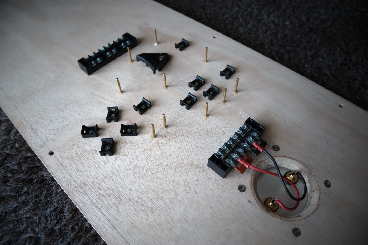
In the photo above you can see all the parts needed to construct one enclosure. At this point I had already glued a separate smaller enclosure for the coax drivers to the front panel, made out of a cardboard tube. The enclosure can be assembled from the pictured parts just by screwing the aluminium extrusions together.
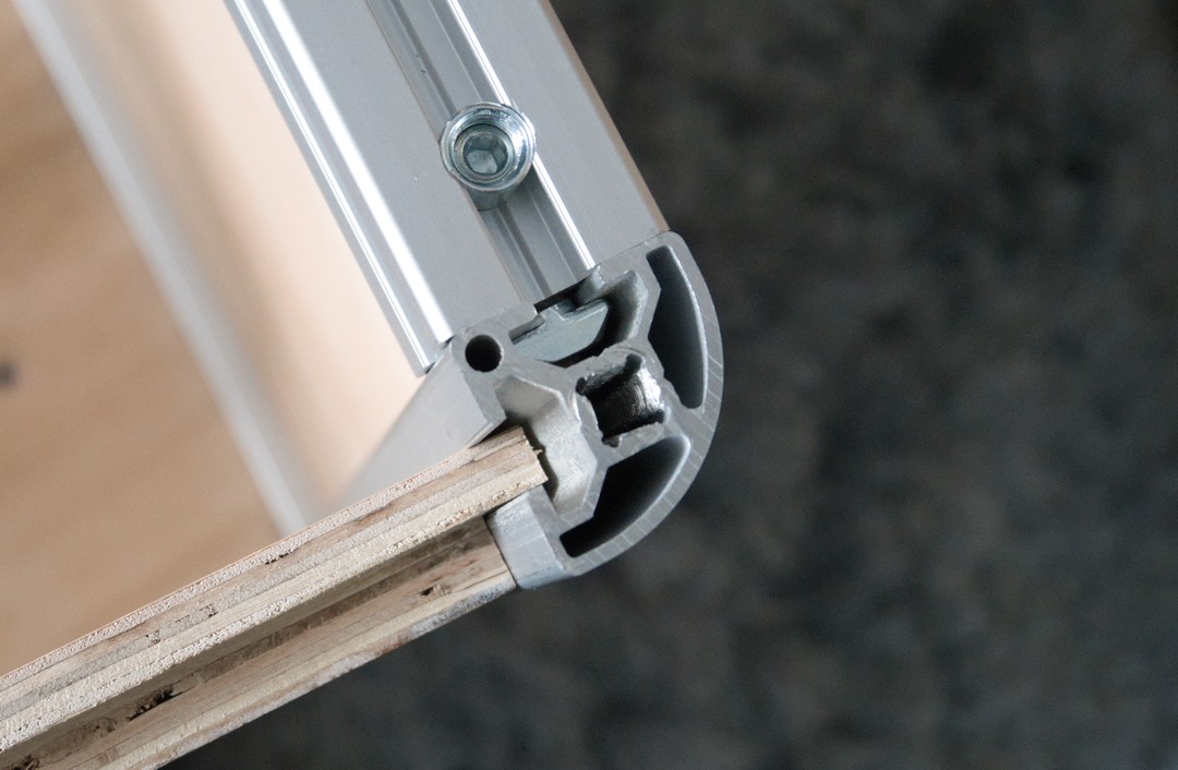
The extrusions have slots along their length, allowing a rabbet cut on the edge of a panel to be inserted. If the dimensions are accurate enough, this can be a tight fit, though it's not going to be completely air-tight. With appropriate choice of panel thickness, the outer face can be made to sit flush with the aluminium parts.
Fortunately, it all fits together nicely. I was slightly concerned that the aluminium parts might ring, and indeed the frame by itself sounds like a bell when tapped, but once the panels were installed, everything was damped better, and it sounds no worse than a normal all-wood enclosure when tapped.
I happen to have access to a load of packing material made from recycled jeans that looks like it will work well for absorbing sound. I attached plenty of it inside the enclosures to help absorb reflections.
Crossover
Before trying to work out how best to cross these drivers over, I measured their frequency response using REW.

The mid and tweeter responses look similar to the published responses (there is no published response for the woofer), including the mid's unpleasant lump at 6.5kHz. Interestingly, the woofer has one at exactly the same frequency, but for a woofer, it's too high to care about.
Given the frequency responses, I chose crossover frequencies of 400Hz and 4kHz. 2nd order for the woofer/mid, and 1st order for the mid/tweeter. Although a 1st order crossover will not adequately suppress that 6.5kHz peak, I wanted to use one anyway, as one of the theoretical advantages of coaxial drivers is that they don't need such steep crossover slopes, and I wanted to take advantage of that.

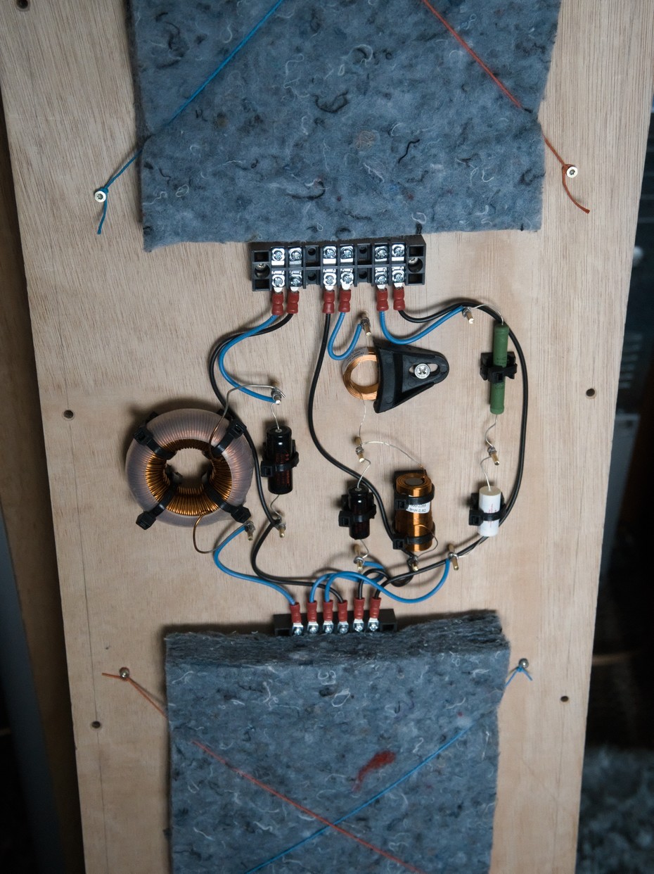
After much fiddling, I arrived at a design that would work with standard value components. A little bit of padding was needed for the mid, and a little more for the tweeter. I splashed out on nice components, including some spiffy Jantzen C-Coil toroidal inductors for L1. Their toroidal shape minimizes the external magnetic field they emit, meaning less worry about how they are oriented relative to the other inductors in the crossover. For L2 I was conveniently able to choose an inductor with a DC resistance of 2.5Ω, so no physical resistor was needed for R1.
Since some of the components are too large and heavy to mount on a PCB, I constructed the crossover like an old-fashioned breadboard, with brass pins inserted into the enclosure's rear panel, and component legs and wires soldered to those pins.
Finally, I took some measurements to make sure the crossover actually worked as intended.

It looks reasonably flat. Since this was measured the same as before, 30cm away at the height of the tweeter, it's mostly missing the bass output from the port, making it look like it rolls of sooner than it really does. It's possible to take multiple measurements and combine them into a single frequency response plot, but I'm too lazy to do that. I did measure the port alone though, at a distance of 0cm, right in it's mouth.

This shows that the response does indeed extend quite low. At normal listening distances, the port output will be added to the output from the drivers. It's useless trying to measure the response that far away, as reflections will completely destroy any semblance of flatness.
Installation and Listening
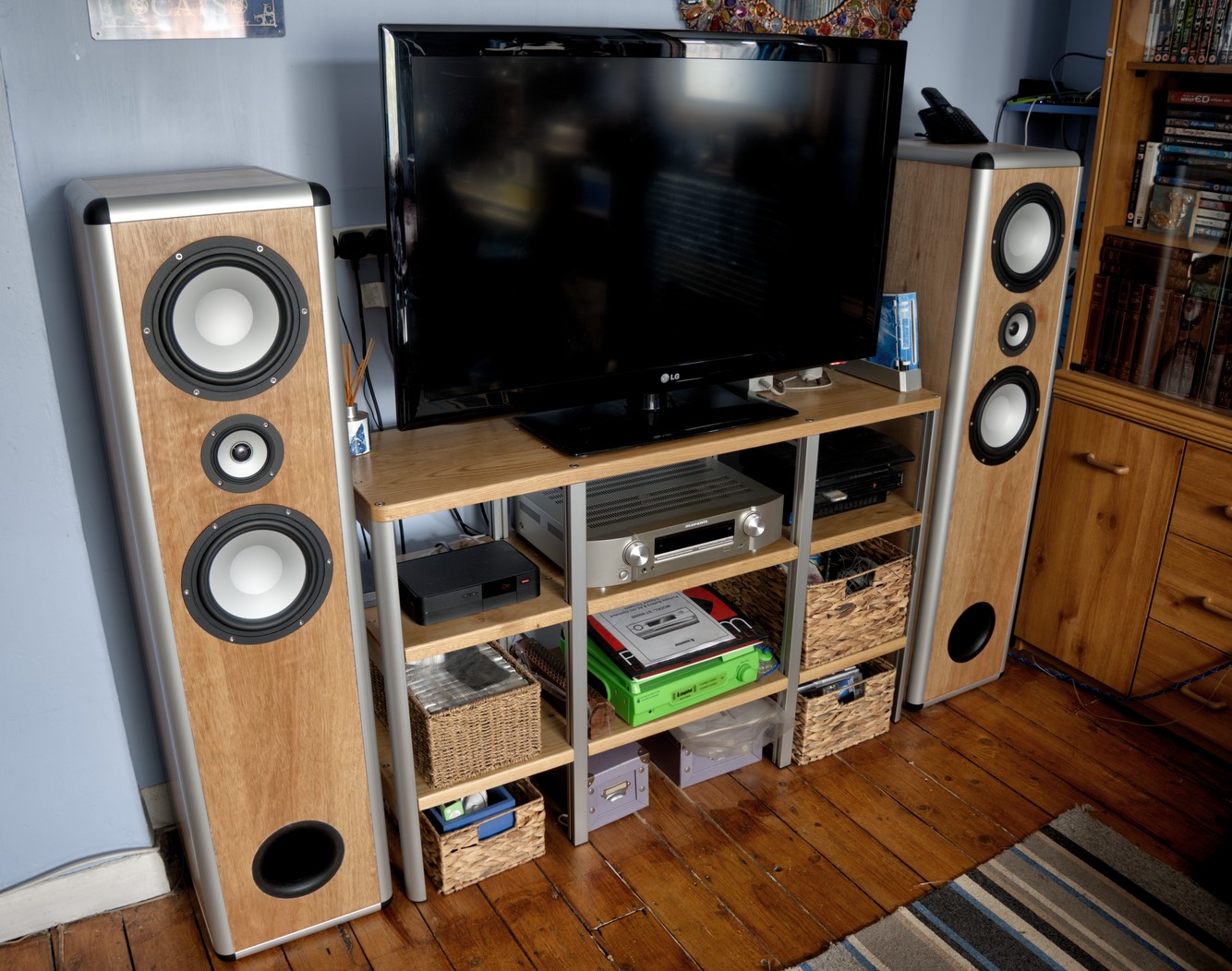
As you would expect from speakers this large, they cover the full audio spectrum without needing a subwoofer to fill out the low end, and are capable of doing so at a more than adequate volume. This is perfect for watching films. They work great for music too, just begging to be turned up to neighbour-annoying levels. And it turns out that constructing speakers from T-slot aluminium extrusions can work ok.