Amp4 - Subwoofer - Power Supply 1
The circuit is taken straight out of the datasheet. I made it variable so that it can be reused in future projects if needed (regulated power supplies are always useful for something). It could supply more current if a higher voltage transformer were used, at the expense of increased power dissipation. With the 15-0-15V one I've used, the input voltage drops too low for the regulator to maintain a 20V output at around 200mA; more than sufficient for the amp, which requires only 20mA or so.
Schematic
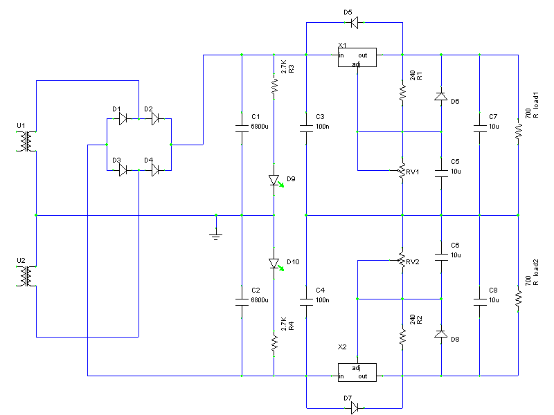
I have included protection diodes around the ICs, just in case of accidents. The LEDs provide a quick visual indication that the reservoir capacitors are charged and that the fuses (not shown in the schematic - they're between the reservoir capacitors and the LEDs) are not blown.
PCB layout
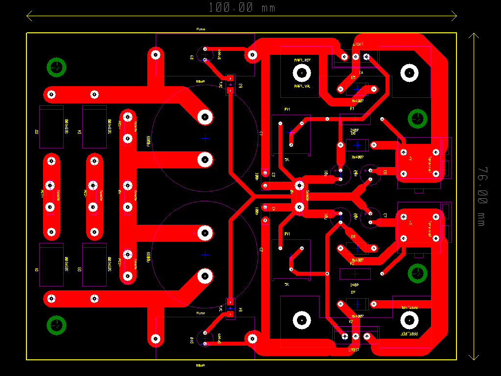
Rectifiers and reservoir capacitors are included on the PCB to keep things compact. Ground from the reservoir caps/transformer is kept separate from everything else on the PCB, being connected at the main star-ground, which is a copper strip bolted to the case. There is also a local star-ground on the PCB. LEDs are mounted under the fuse holders, which just happened to have convenient screw holes there!
Building and testing
Here's a photo of the thing assembled:
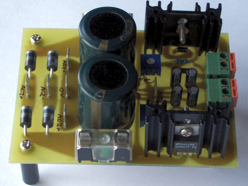
Not much to say about it. These ICs are very reliable and easy to use, so it all just works.