Rush Cascode Input Stage
Conventional 3-stage amplifiers use a long-tailed pair as the input stage. Although it is not obvious, the LTP is a cascade of a common-collector followed by a common-base amplifier. This can most easily be seen by looking at a complete amplifier in an inverting configuration, as in the following schematic.
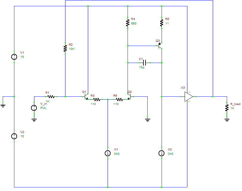
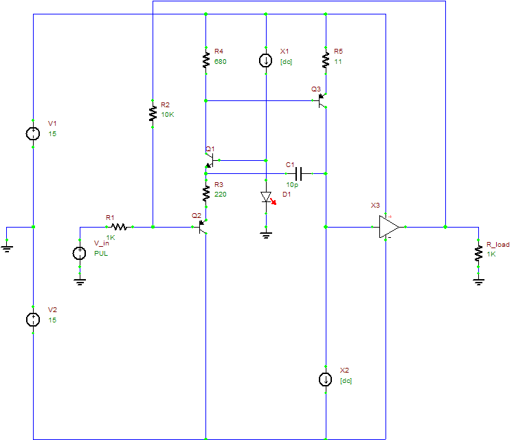
For Q1, its base is the input, its emitter is the output and the collector is common, i.e. it's a common-collector amplifier. For Q2, its base is the input (from the output of Q1), its collector is the output, and its base is common, i.e. it's a common-base amplifier. This is not particularly interesting in itself, but viewing the LTP like this did make me realize that two configurations of transistors can look very different but actually be very similar. More specifically, it made me think of the circuit sometimes known as the "Rush Cascode", which is also a common-collector stage followed by a common-base stage, except it uses one transistor of each polarity instead of two of the same polarity. It's a rarely used circuit, although it is used in the input stage of the famous 741 op-amp, in a somewhat different way to how I am using it here. The following schematic shows the obvious way to replace a LTP with a Rush Cascode:
While it may be topologically similar to a LTP, this input stage configuration has some significant differences, such as:
- Class AB. This means it can supply a much higher output current than a LTP (which is limited by its tail current), with consequently higher slew rate (although only in one direction - the other direction is still limited by the Vas current source).
- The two outputs are in opposite directions. This makes it hard to use a current mirror to double the gain like you can with a LTP.
- The DC offset is highly dependent on device parameters and temperature.
- The non-inverting input (at the LED's cathode) is low-impedance, and sinks the LED bias current, making it unusable as an input.
- No cancellation of 2nd harmonic distortion.
- PSRR is not as good.
Since it uses about the same number of components as the conventional LTP, I decided that it would be fair to do some simulations and measurements to compare the performance of the two circuits.
For the measurements, I built both circuits on a breadboard, using BC5x6B transistors which I matched for hfe (which doesn't give perfect matching, but it's quick and good enough). For the output stage I used my diamond buffer module.

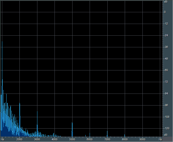
The spectra are broadly similar for both circuits, except for the 2nd harmonic being substantially lower for the LTP amp, as expected. Adding up the numbers says that the LTP amp has a THD of 0.0014%, and the Rush Cascode amp 0.0024%
I also measured slew rate, which was about ±70V/μs for the LTP amp. The Rush Cascode amp was too high to measure in the positive direction using my 'scope (>1000V/μs), while in the negative direction it was about -70V/μs, just like the LTP amp.
Other parameters are hard for me to measure, so I made the following simulations:
| LTP | Rush Cascode | |
|---|---|---|
| PSRR+ | 56dB | 45dB |
| PSRR- | 56dB | 50dB |
| Loop Gain | 55dB | 55dB |
| GBW | 3.7MHz | 4.0MHz |
| Phase Margin | 78° | 77° |
| Gain Margin | 22dB | 22dB |
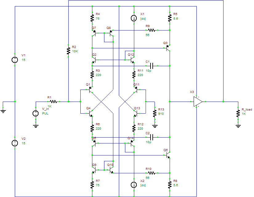
There's not a lot in favour of the Rush Cascode input stage at this point, so I tried some modifications to fix its shortcomings:
- Added a second, complementary input stage in parallel with the first. This raises the negative slew rate up to the same level as the positive slew rate, helps cancel 2nd harmonic distortion, and increases PSRR (because variations in rail voltage now affect both halves of the circuit, partially cancelling).
- Added current mirrors. The addition of the second input stage makes this possible because there are now two outputs available in each half of the input stage. This increases the gain. Note that I had to add a little current feedback around the Vas to ensure that its quiescent current is defined.
- Replaced the bias LEDs with transistors matching the input stage transistors. Bias current is now dependent only on matching between pairs on transistors, and if they are thermally coupled then temperature stability will be good too. Furthermore, the extra transistors serve to buffer the inverting input, making it useable.
Measurements of the modified Rush Cascode amp showed a THD of 0.0013% (unfortunately I misplaced the FFT of this), which is a definite improvement, but not spectacular. Slew rate is now too high to measure in both directions (>1000V/μs).
Lastly some simulations:
| Modified Rush Cascode | |
|---|---|
| PSRR+ | 52dB |
| PSRR- | 52dB |
| Loop Gain | 74dB |
| GBW | 7.0MHz |
| Phase Margin | 49° |
| Gain Margin | 14dB |
PSRR didn't improve by as much as I expected, but it's acceptable now. These improvements come at a cost of complexity though. In conclusion, it's an interesting circuit, but not really an improvement over the standard LTP unless huge slew rates are required.