Solar Light
We have a lot of solar lights in our garden, and I spend quite a lot of time fixing them when they inevitably fail after a short time. It is frustrating that there are a few failure modes that occur across all the various designs, both cheap and expensive, most of which seem fairly obvious and easy to avoid. As industry has failed to solve them, I decided to make a solar light of my own. Some of the problems that I hoped to avoid include:
- Battery failure. Batteries can only sustain a limited number of charge/discharge cycles before they start to lose capacity. This is made worse in solar lights where the battery is often discharged completely, and subjected to extremes of temperature.
- Battery contact failure. Usually due to rusting.
- Switch failure. Also usually due to rusting.
- Solder joint failure. Poor quality soldering and exposure to the elements causes joints to crack.
- Broken wires. Presumably to save money, the internal wiring is often incredibly thin and made of unplated copper, which corrodes through quickly.
- Solar panel failure. Better panels are covered with UV-resistant epoxy or glass, but the cheap panels in these solar lights often use some sort of plastic that eventually becomes opaque from exposure to sunlight. Some panels aren't even sealed properly around the edges, allowing water to seep in between the layers.
- Water damage. Beyond the corrosion problems mentioned above, which can happen due to humidity and condensation alone, many solar lights are not well sealed against rain, and can even fill with water completely.
The foundation of my design is the use of a supercapacitor in place of a battery. These can survive a much, much higher number of charge/discharge cycles than batteries, will put up with large swings in temperature better than batteries, don't have any problems with rusting contacts (because their long life allows them to be soldered in place permanently), and can be discharged all the way to 0 without harm, making an on/off switch unnecessary. Though they have become more affordable recently (about £3 each when purchased directly from China in small quantities), this still immediately puts the cost above the cheapest lights in their entirety.
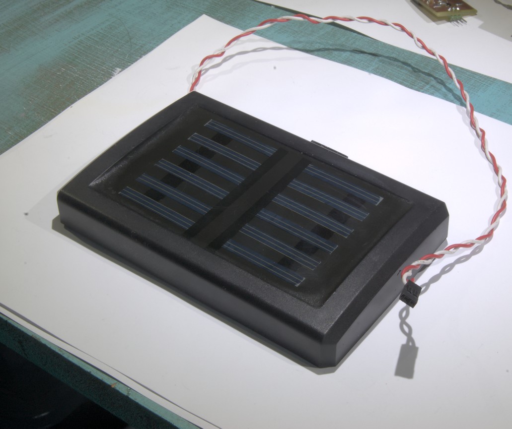
I also wanted to reuse a solar panel from a failed commercial light. Despite the failure of the light it was taken from, the panel itself had survived outside, so I deemed it suitable. Measured in the late summer noon sun, the solar panel has VOC = 7.1V and ISC = 60mA. From that, and some measurements of the V-I curve of the panel, I worked out that PMPP = 320mW, which is a pitiful amount of power even for such a small panel, but enough for some LEDs.
The rest of the problems could be solved by generally choosing materials of adequate quality, and not constructing it incompetently.
DC-DC Converter
Because the output voltage from the panel is much higher than the 2.7V maximum of a supercapacitor, I needed to step down the voltage. I wanted to perform MPPT to squeeze the last few drops of energy out of the panel, but that would have required more sophistication than seems appropriate for a piddling little garden light, so I just made a simple hysteretic buck converter.

In the above schematic, D3 is an LED that I measured to have a VF of 2.7V, conveniently the same as the maximum voltage of the supercapacitor. This allows it to be used directly as a voltage reference for U1A to limit the output voltage. Most of the time the supercapacitor is not fully charged, so U1A sits idle. It's U1B that drives the circuit by comparing the reference voltage to the solar panel's output voltage. While C1 is charging, U1B holds Q1 off. When C1 is charged enough, it switches Q1 on, transferring energy from C1 to the supercapacitor via L1. Once C1 has been discharged back down below the hysteresis threshold, Q1 is turned off again and the cycle starts again. This keeps the voltage across the solar panel within a narrow range around 4.5V, which is high enough to reach a decent fraction of PMPP when it's sunny, but low enough that it can still extract some energy on dingy winter days.
U1 must have a push-pull output in order to turn Q1 off reasonably quickly, and it needs to be able to operate with a supply voltage down to about 3.5V. I chose a TS3702 for this. The other components aren't so critical, but efficiency is improved by using schottky diodes for D1 and D2, and choosing an inductor with low series resistance for L1. The switching speed of the circuit is determined by the size of C1 and the current from the panel. Since the current varies, the switching speed also varies, from a few kHz up to tens of kHz. L1 must be big enough to not saturate when current from C1 is dumped into it.
There are a total of 15 components, excluding the solar panel and the supercapacitor. It would have been 14, but on testing the circuit on the breadboard, stray capacitance across R5 caused U1B to switch off Q1 too soon, and I had to add C2 to compensate. Also, the circuit will operate just fine without D1, but it is required so that the solar panel can double as a light level detector to turn the LED driver on when it gets dark (without D1, the MOSFET's body diode would prevent the voltage across the panel from falling below the voltage across the supercapacitor). That's 15 more components than most commercially available cheap solar lights which just connect the solar panel directly to a battery, but it's more efficient.

I used through-hole components for the PCB as it doesn't matter how big it is. The loops which carry switching currents are kept as close to the supercapacitor as possible, although it doesn't switch very fast, so that's not too important. The circuit is simple enough that a single-sided board suffices.
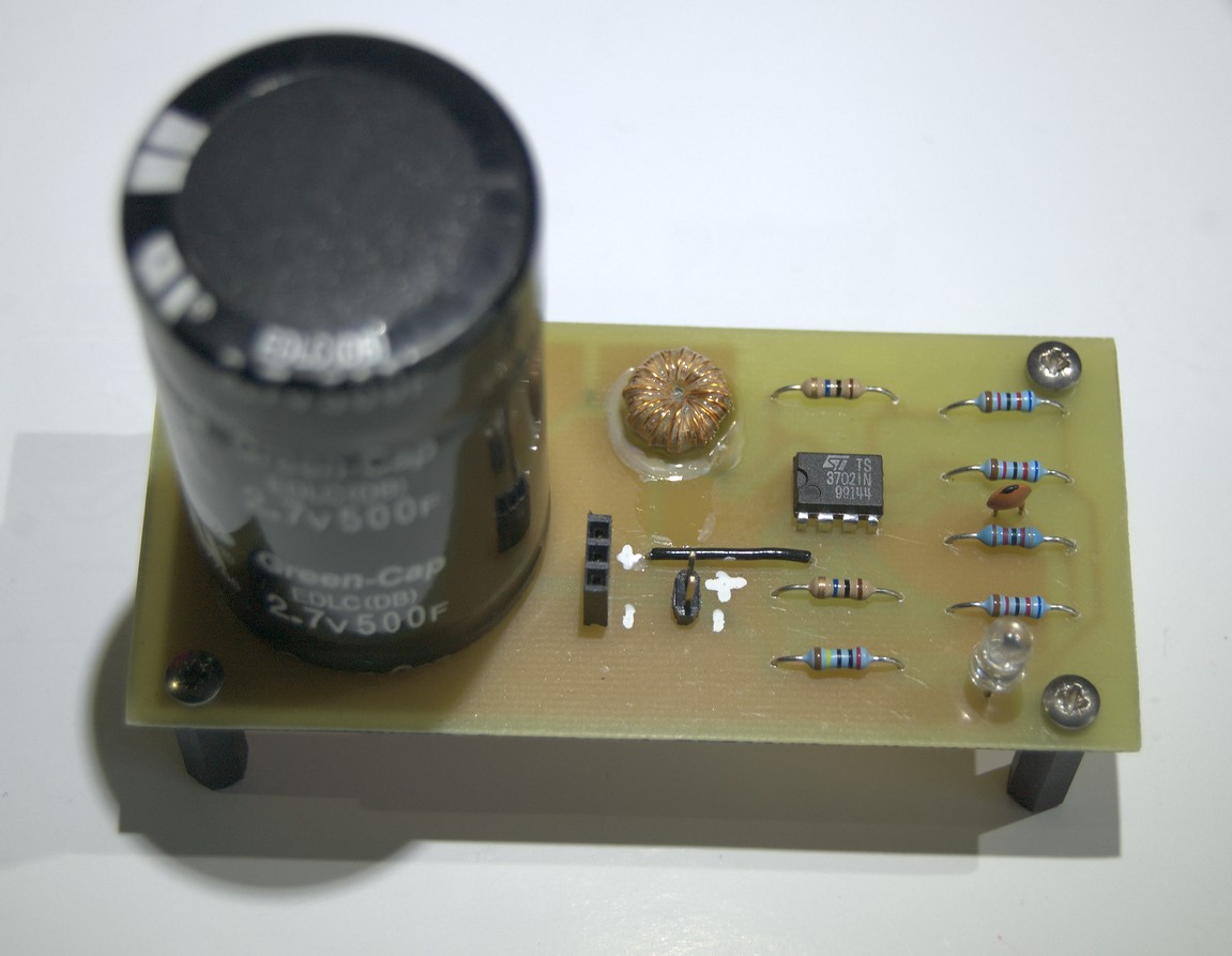
The PCB was made by hand, using the laser printer toner transfer method. The inductor is one I pulled out of an old power supply. It's rather loosely wound, so I smothered it in glue to stop it from vibrating. Annoyingly the glue did nothing to stop it from emitting a high pitched whining sound as it oscillates in the audible range. The measured efficiency at typical operating conditions is 85%, which is ok.
LED Driver
To drive the LEDs, I chose the LT1932. It's not cheap, but it doesn't require an external switching transistor, it will work with an input voltage down to 1V, and has a high enough output voltage to easily drive the three LEDs that I wanted to use. If I had used two supercapacitors in series to get a higher voltage, then I could have chosen a cheaper LED driver, but that would also have required either a higher voltage solar panel, or a more complicated buck-boost DC-DC converter.

Q1 inverts the voltage from the solar panel so the LED driver is turned off when it's light, and on when it's dark. I was hoping that once the supply voltage dropped low enough, the LT1932 would shut down, but it can't cope with an analogue voltage on its enable pin, so as the supercapacitor drains too low for it to light an LED, the driver continues to draw a little bit of current until the supercapacitor drains further. The value of R4 was chosen so this happens once the supercapacitor reaches 1.1V, then it drains down to 1.0V. That's a small enough loss that I didn't think it worth adding more components to fix it (which would be hard because 1V is not enough to power a comparator), especially compared to many of the commercial lights which behave even worse.
The output current is set to 4mA, which might seem low, but it actually looks very bright outside at night.
Note that Q1 is labelled as a 2N7002 in the schematic, but actually I don't know what it was (it was out loose in one of my parts drawers, and SOT23 packages are too small to be labelled fully). Any MOSFET would work here, but the threshold voltage determines when the light switches on, so a low-threshold MOSFET is best (not a 2N7002).

The LT1932 switches at 1.2MHz, so the PCB must be kept small by using surface-mount components. The datasheet demanded a multi-layer board, but I assumed this was more to prevent it causing interference than for the operation of the circuit itself, so I made it a single-layer board, which appears to work fine.
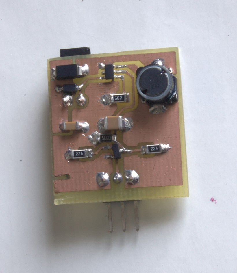
Those with an eye for detail may wonder why R4 and D2 look like they have been squeezed in as an afterthought. That's because they were squeezed in as an afterthought. R4 was added once I discovered that the LT1932's enable pin doesn't like analogue voltages, and D2 was added after I discovered that the datasheet's warning about not operating the chip without an LED connected was serious. Normally these issues would be worked out on the breadboard, but a circuit this fast would never work on a breadboard, so I had to fabricate a proper PCB straight off.
Housing
To make it look like a proper light and not just a pile of electronic parts, I put everything in an old paraffin lamp that I acquired a long time ago.

This lamp was designed to be used outside, so it should cope with the rain. The lenses on the side are amber, so the obvious choice of LED would be amber too, but amber LEDs are about the least efficient of all the available colours. Slightly more efficient amber LEDs are available which use a blue LED with phosphor to change the colour, the same as white LEDs do, but they are still less efficient than using white LEDs and just wasting all the non-amber light
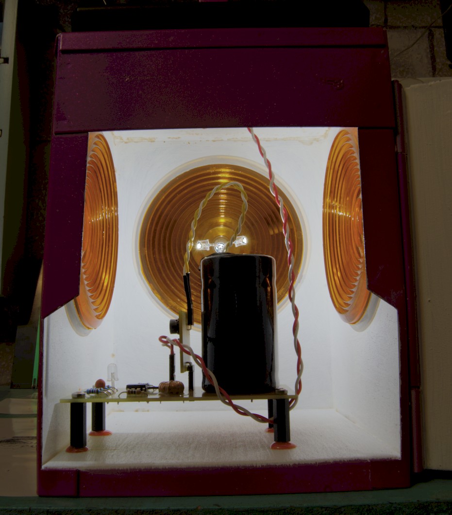
I attached the PCB such that the supercapacitor is in the centre of the lamp, then the three LEDs could be stuck on top to line up with the three lenses. The wire coming down from the top is from the solar panel. Note that I deliberately looped it underneath so that any water that drips down it falls off rather than flowing straight onto the PCB. I sprayed the PCBs with conformal coating to help prevent corrosion. This is especially useful for hand-made PCBs that lack solder-resist over the copper.
The use of pin headers to connect the LED driver and solar panel is a potential weakness, as they could corrode. They started out like that because I needed to disconnect them many times during testing. I can just solder them in instead if they prove unreliable later.
Completed
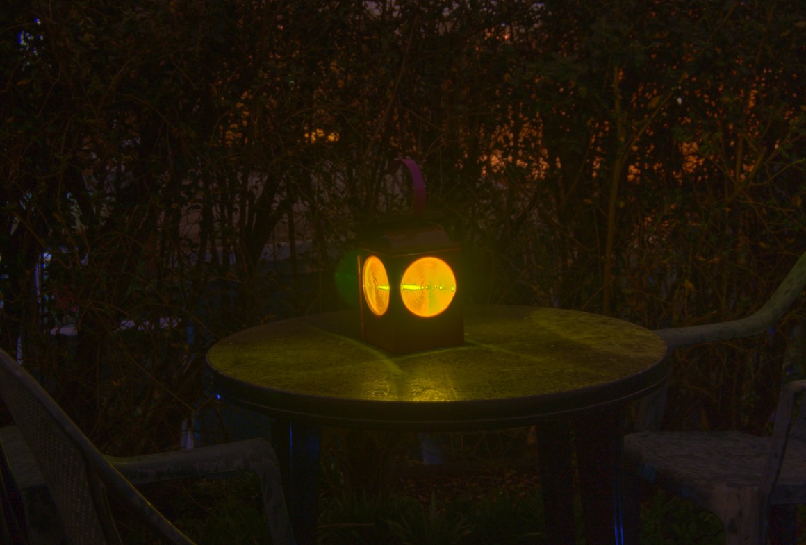
It gives a couple of hours of light output after charging over a cloudy day in winter, which is ok considering it produces quite a lot of light. I won't know if I have succeeded in creating a reliable device until it has survived outside for a few years.
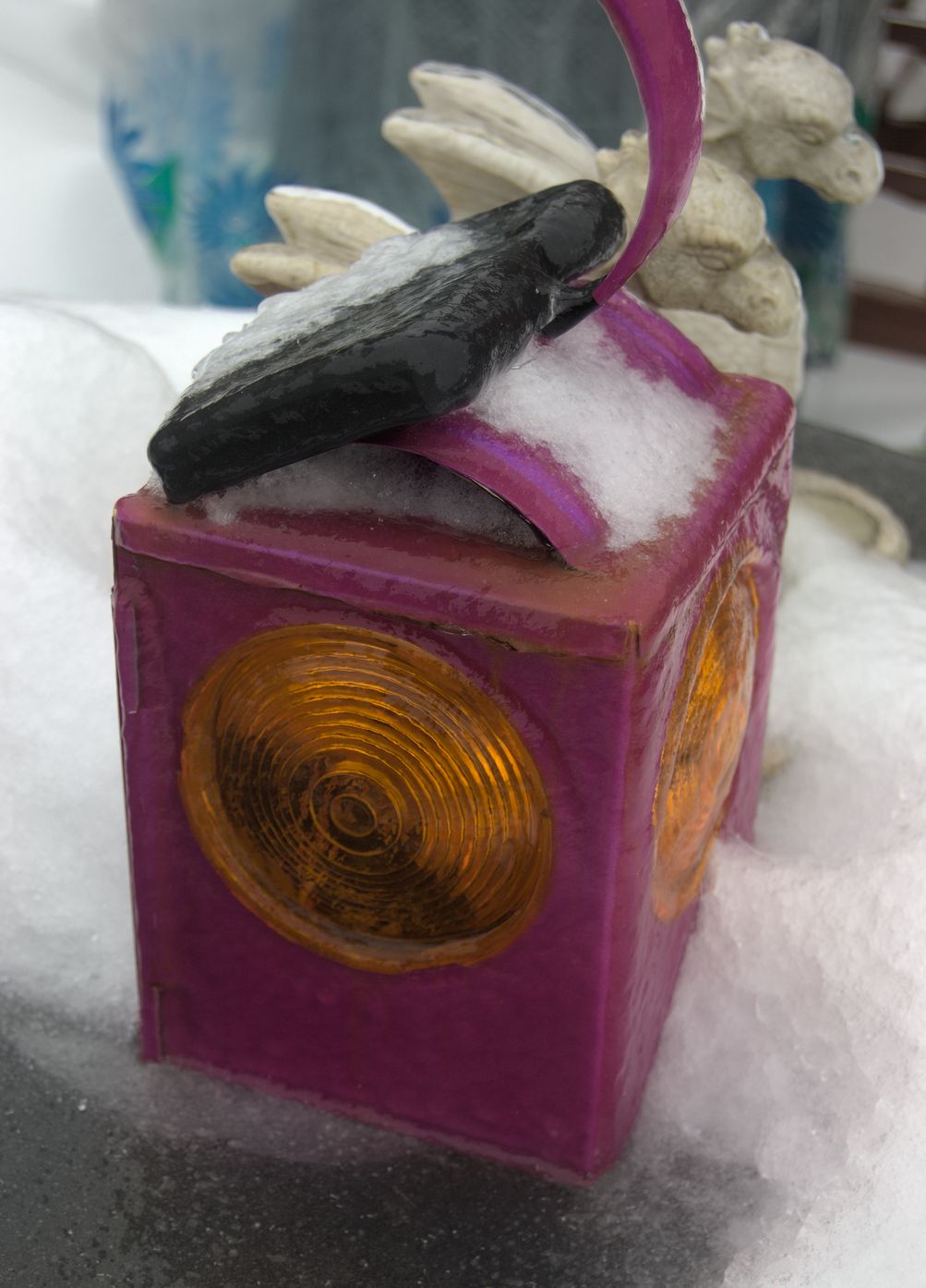
Update, 2018-03-05: After one year, the light was hit by snow and freezing rain, covering it in ice, and making for an interesting photo. It still works.
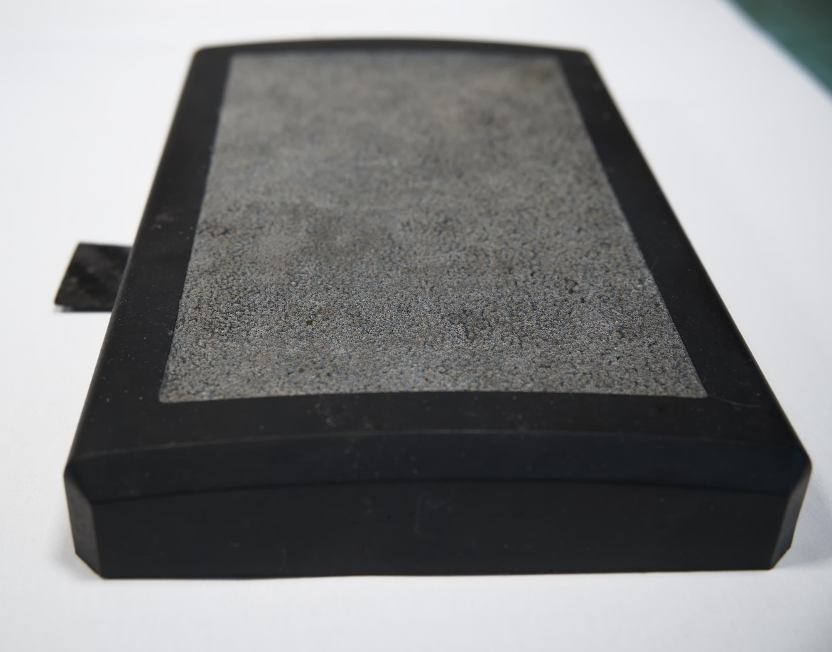
Update, 2022-11-20: After nearly 6 years, it finally had to be repaired. The part that failed was the solar panel, which had clearly been constructed using materials unsuited for exposure to the sun. Whatever the material covering the silicon cells themselves was, it had degraded to the point where it was no longer transparent, so the panel no longer generated sufficient current even under bright sunlight. Disappointing, but 6 years is not bad for a part that had been salvaged from an already broken light.
It's easy enough to fix by simply replacing the panel. Instead of a direct replacement, I purchased a larger panel and fitted it to the rear side of the lamp instead of on the top. This looks much neater, but isn't angled at the sun, so it won't capture as much light. The larger size of the new panel makes up for that, so it still charges up fine even on cloudy winter days.
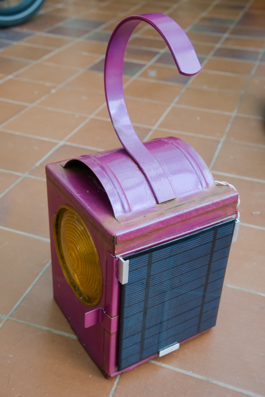
The metal lamp housing is beginning to rust too, though it should be good for at least another 6 years.