Amp4 - Subwoofer - Speaker
Wanting something different to the normal sealed or vented boxes, I played with a variety of unusual designs, but finally settled on a horn as the best, giving high efficiency, low distortion and good low-frequency extension. The only problem is the enormous size required. To solve that problem, the horn serves a dual purpose as a piece of furniture - a bed.
Design
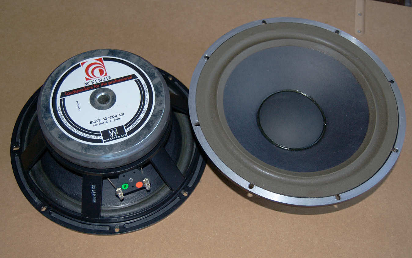
I already had a spare pair of Mckenzie Acoustics 12" woofers which are fairly well suited to horn loading (low Qts of 0.21), so I could go straight on to designing the horn itself. I used Hornresp to design the horn, which makes it very easy to tweak the design to reach the desired result.
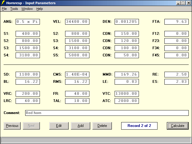
With the two drivers wired in parallel for 4Ω, sensitivity should be 110dB@2.83V@1m, and still over 100dB at 20Hz when corner loaded, so very little amplifier power is required.
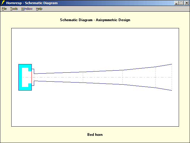
The total path length is over 4m, so some folding is required to make it bed-shaped. To work out how to fold it, I whipped up a quick model in Unreal Tournament 2004's (and later UT3's) editor. UEd lacks CAD features, but it is pretty good for quick visualization.
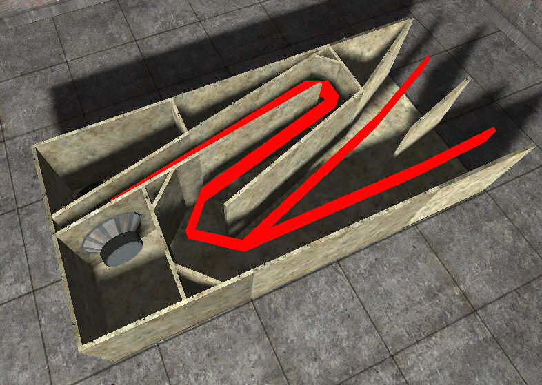
The above image shows what I ended up with. The compression chamber and throat have been merged to simplify the layout. Mounting the two woofers opposite each other should result in vibration cancellation.
Since the bed is far too massive to move as a whole, it is designed to split into three sections. It's easier to build smaller sections too.
Construction
About four years passed between when I designed this and when I actually got around to building it, but it's done now. As usual, everything is constructed of MDF. I like MDF because it's cheap, very consistent and isotropic, and easy to work with (remember to wear a mask because the dust is toxic). I used 18mm thick sheets for most panels, with a few of the very smallest panels being 12mm. Thicker MDF might have been better, but would have been impractical due to weight. Some careful measuring and cutting was required to get the angles right, but otherwise it was fairly straightforward. All panels were secured with both screws and glue, except the top panel of section 1 which was only screwed, so it can be removed if I ever need access to the drivers again. Most joins were also sealed with silicone sealant to be doubly sure that they are airtight.
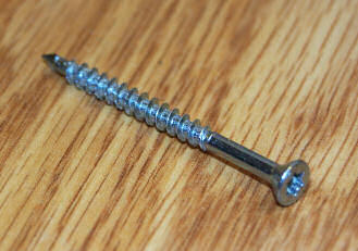
I recently came across Spax screws, so I bought some of those. They have torx heads, which I like because they never slip and are virtually impossible to chew up. They self-drill so well that they will go into the edge of 18mm MDF without causing splitting even with no pilot hole (thinner MDF still requires a pilot hole though), and they self-countersink too (which actually isn't so good if they are removed and replaced more than a few times, because they end up digging really deep holes). Overall, they save a lot of time compared to the usual chipboard screws, but they are relatively expensive.
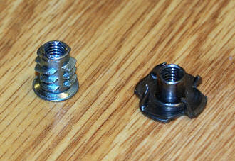
I also switched from using common t-nuts to screw-in threaded inserts. They have some advantages over t-nuts because they take up less space (important if they are used very close to a driver cutout) and should hold better, but they do tend to unscrew themselves if the bolt becomes cross-threaded while being tightened.
I coated all the panels inside and out in acrylic-based MDF sealer. This serves the dual purpose of preventing the final paint finish from soaking into the MDF, and on the unpainted parts it should help to resist moisture (bare MDF likes to suck up water when the humidity is high, which is all the time in the UK).
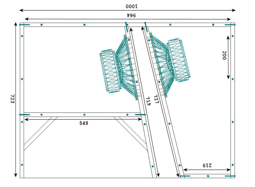
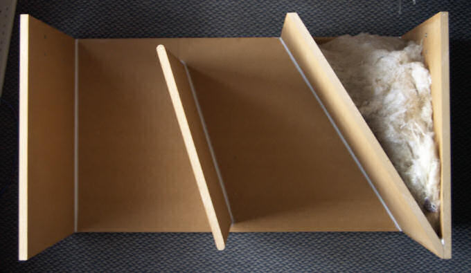
Section 1
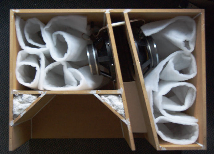
In the above picture you can see a small white tube in the throat above the woofers. This is just a conduit so the cable from one woofer can be run to the connector which is in the other woofer's enclosure. The two "dead" corners in the lower left are stuffed with some... stuff. It appears to be a mixture of artificial and natural fibres, which I put in there with the intention of damping any resonances in the otherwise empty spaces. The stuffing in the rear chambers is ordinary polyester wadding.
One addition not in the original plan is the brace across the throat of the horn, just past the woofers. This should help couple the two sides together for better vibration cancellation. It would probably help if there were also some bracing in the rear chambers, since the panels are not very thick for their size, but I don't think it would be worth the extra weight.
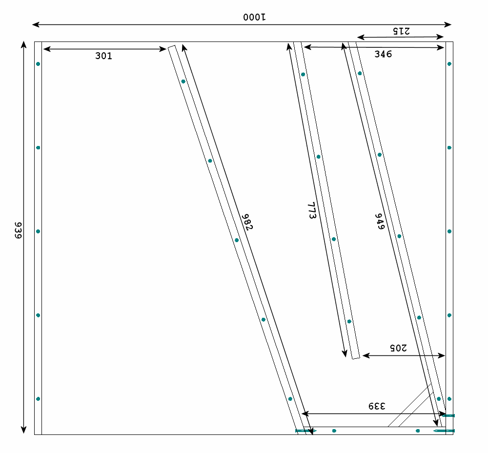
Section 2
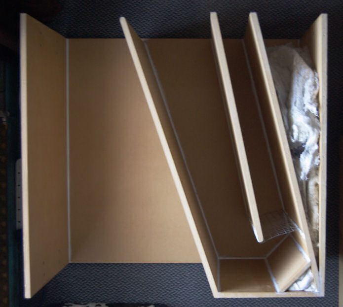
The empty spaces have again been stuffed with fluff. Also visible just before the first bend, at the lower right of the photo, is a metal grille. This is to prevent curious feline interlopers from reaching the precious drivers.
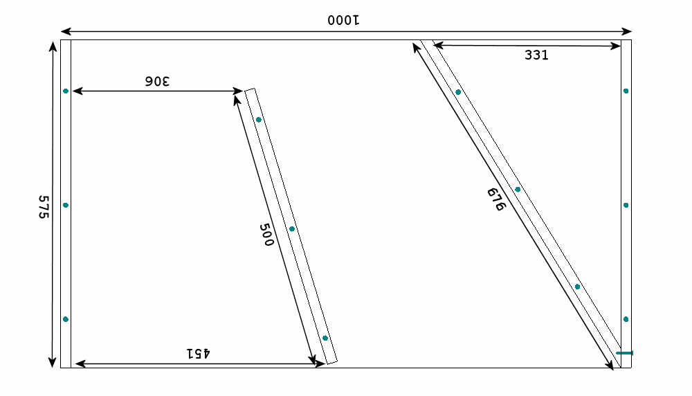
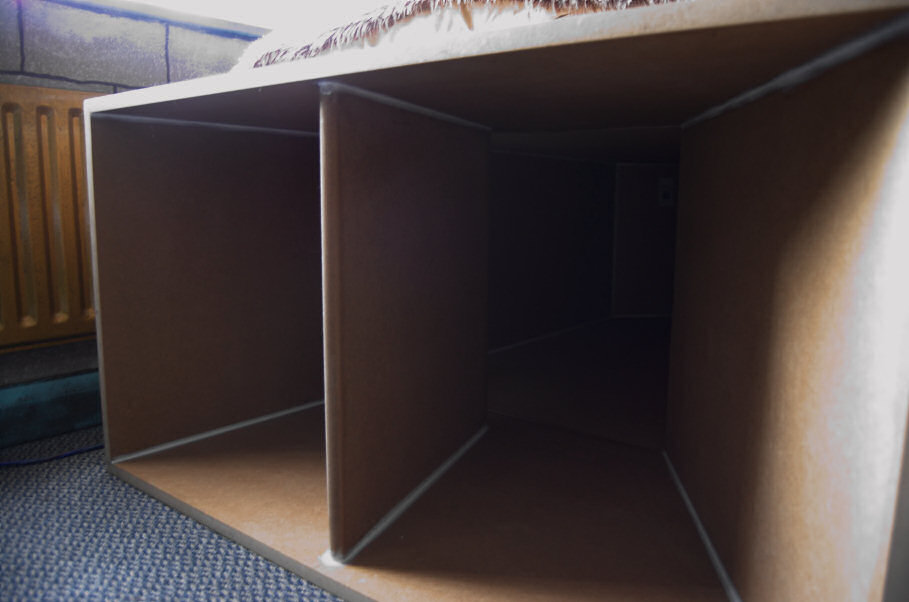
Section 3
This is the smallest and simplest section. Proportionally, it has the largest wasted space, stuffed with the same fluff as the other spaces. The extra panel down the middle of the mouth is just to support the top panel.
Completed bed
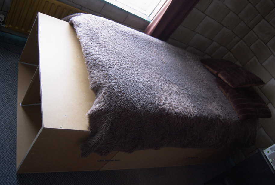
I have left the MDF bare for now, until I decide how best to finish it. I used metal straps and bolts to hold the sections together, and sealed the joins with foam strips. This turned out to be really difficult to assemble because the straps do not pull the sections together and the foam is not quite compressible enough. This was not helped by the fact that the floor is not level, causing the gap between sections to vary, requiring thick foam in places and thin foam in others. I did manage to get it all together in the end though.
Testing
The first thing I had to do after firing it up was turn it down a lot relative to the satellites, due to its high efficiency. With the levels matched approximately, I gave it a listen and was greatly pleased at the loud, low bass. It's very obvious just how low this sub goes, because it quite happily produces noises that can be felt but not heard (I tried playing a 20Hz sine wave at high volume, and it made my head feel really weird). The sound is very clean, and it blends in quite well with the satellites considering how very different in design they are.
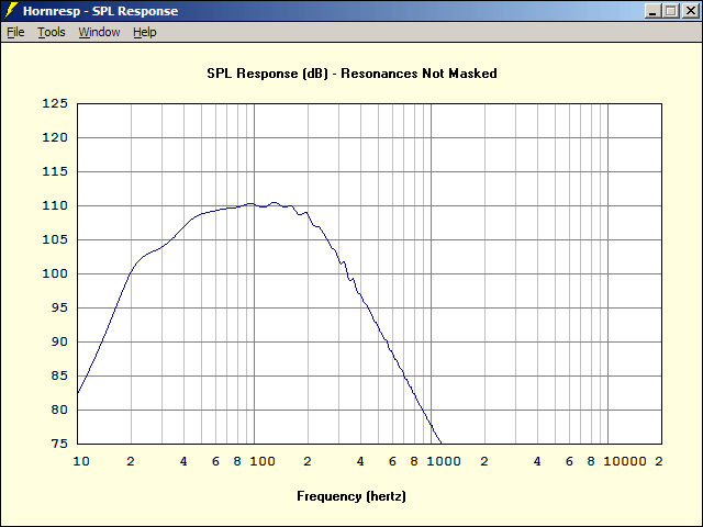
Next, I did a bit of measuring. I only have some unidentified microphone capsule I pulled out of an old tape recorder, so the measurements are probably not at all accurate, but they give some idea of what's going on. I placed the mic right in front of the mouth, which should reduce the effect of the room on the measurements. I repeated the test in other locations of the room, but it didn't actually make a lot of difference.
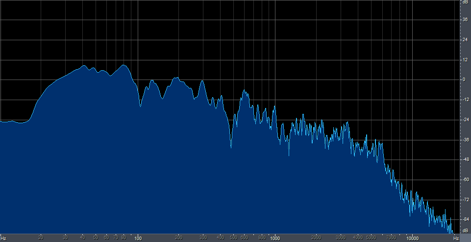
The first thing that's obvious about this graph is that the response extends much higher than the Hornresp graph. This is the direct contribution of the drivers themselves without the horn. Perhaps I should have put some stuffing at the corners to absorb the higher frequencies instead of letting them bounce around, but it's not a problem because the input to the sub is low-passed anyway.
The second obvious feature of the graph is the two deep notches at ~105Hz and ~470Hz. I presume that these are resonant modes of the horn itself, with the first section of the horn being approximately 1/4 of a wavelength at 105Hz. I'm not sure where the one at 470Hz comes from. I might try a bit of stuffing in there to flatten that out.
There are a lot of other peaks and troughs in the graph, and a kink below 15Hz, but mostly they are just due to the crappy microphone and passing cars, as well as the room itself.