WiFi Lighting
The motivation for this project came after I completed a previous lighting project which had physical controls. It was inconvenient having to walk over to the controls every time I wanted to change the colour, or switch the lights on/off, so for this project I wanted something that I could control from anywhere, whenever I wanted. From those requirements I concluded that the best solution would be to provide a web interface, as it can be accessed over WiFi (works from anywhere, even through walls) using my phone (I always have it with me, so no hunting for a remote control).
Controller
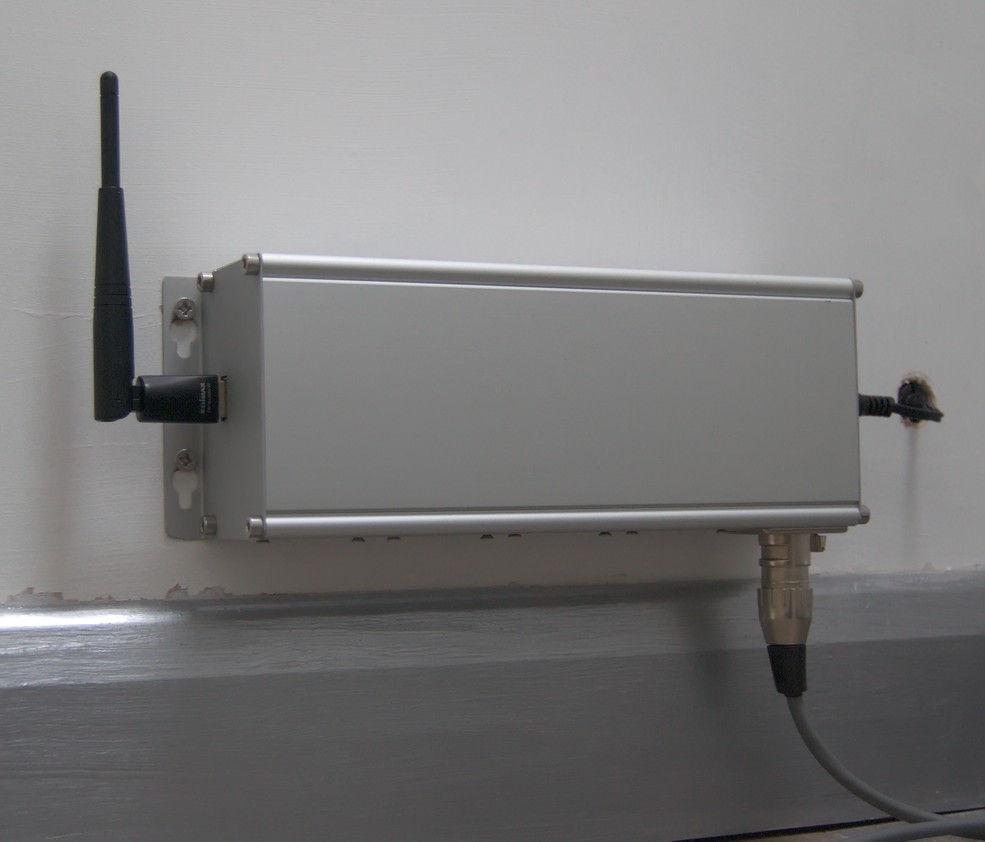
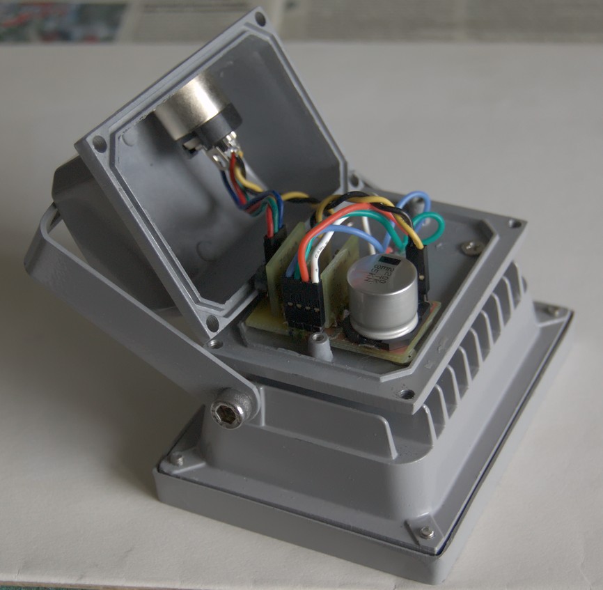
The controller provides the web interface, and outputs PWM signals to control the lights. At its heart is a Raspberry Pi. These are great because they are very cheap, have a decent amount of IO, and their popularity means that there are a lot of resources available for them. For my purposes, these resources include an I2C to PWM interface (PCA9685), and a web API for it (WebIOPi). This stuff is all too easy! I hardly have to make anything at all these days, but just connect some building blocks together. I put the Pi and associated bits into a nice wall-mountable case, and placed five sockets along the bottom so up to five lights can be connected (or four lights if your name is Picard), which is the maximum possible using one PCA9685 (which has 16 outputs, where 3 are needed per light for full RGB control)
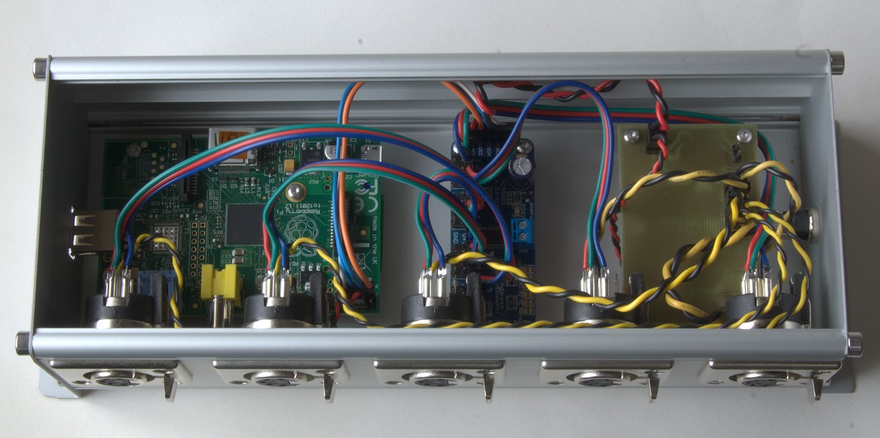
The whole thing runs on a 12V brick. The only part I had to make myself (aside from all the wiring and cutting holes in the case) was the board on the right, which has a large pi filter for the 12V supply (more to stop noise from getting out than from getting in), and a tiny 5V DC-DC converter module to provide power for the Raspberry Pi and PWM board.


Lights
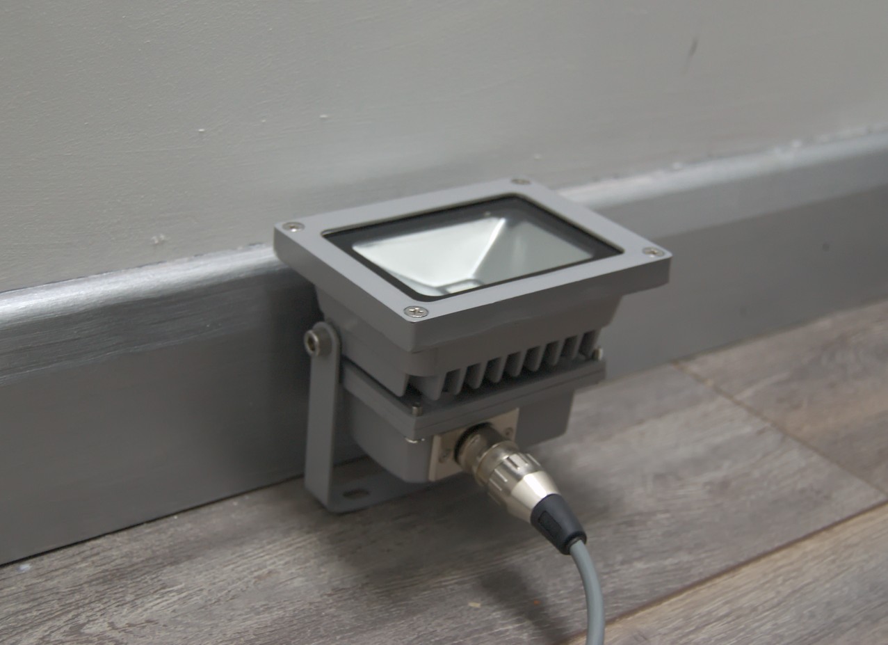
But it wasn't all so easy. As it turns out, it's not possible to buy a simple RGB LED floodlight that can be PWM controlled. They either come with some sort of controller built in, or they are impractically expensive. I decided to go for the cheap remote-controlled ones from China that can be picked up on eBay, and replace the electronics. I don't like wasting stuff, but it's cheaper to get one of these and throw away its controller than it would be to buy something equivalent without a controller. I wanted the lights to be efficient (to keep the current low, so the cables could be thinner), so I built switch-mode constant current drivers to go into them - one each for red, green and blue. They had to be compact to fit inside the floodlight casing, so I used all surface-mount components, and put each driver on its own PCB, mounted vertically. The drivers are connected directly to the PWM signals from the controller.

The NCL30160 chip used for the drivers is slightly unusual - it's one of very few that will work with common-anode LEDs, which is how the LEDs in the floodlights were configured when I got them. It would have been possible to rewire the LEDs to be common-cathode, or independent, and thus use more readily available chips, but I decided that leaving them was easier. Note that I put a pull-down resistor on the PWM input. This is not needed for normal operation, but allows the light to be hot-plugged without it momentarily flashing on at full brightness as the PWM input is disconnected. Although the circuit is very simple, choosing the component values is slightly more complicated due to the maths involved. To aid me in the calculations, I made a spreadsheet from the equations found in the datasheet.

The big capacitor isn't essential, but I had a lot of them left over from the pi filter in the controller, and it does substantially reduce ripple on the supply rail.


Cables
Cables are pretty boring generally, but these deserve special mention. Because I chose to put the LED drivers with the lights themselves, instead of inside the controller (as this makes the controller compatible with any lights I make), I needed to run five wires to each light (12V, ground, and RGB PWM signals). I also wanted the cable to be shielded, to prevent it radiating noise (not strictly necessary, but I really don't like EMI), appropriately colour coded, and it had to be capable of carrying 1 amp over a distance of up to 10m. It turned out to be quite hard to find cable that fitted that description at a realistic price, but eventually I found some from DigiKey. I used connectors on both ends, so the cables can be fixed to the wall while still allowing both the lights and the controller to be removed easily. I chose XLR connectors because they are reliable and common, so I will never have trouble getting more when I want to add more lights. The combination of metal connectors, shielded cable, and metal enclosures for both the controller and lights, means that there is continuous shielding around everything.
Web API
WebIOPi is a very handy bit of software, supporting control of various devices attached to the Raspberry Pi's GPIO header. It needed a bit of customizing to fit this project though. First of all I had to modify it to support more HTTP verbs, so I could make the API RESTful. I have made my modified version of WebIOPi available here. I had hoped that these changes would make it into the official version at some point, but it seems to be a dead project now.
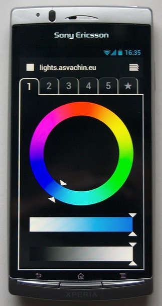
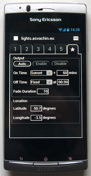
WiFi_Lighting_WebIOPi.zipThen I had to write the actual API, as a custom script for WebIOPi. To install it, put the files onto the Raspberry Pi in /etc/webiopi/ and it should work as soon as you start WebIOPi. The API allows the colour of each channel to be set in the HSV colour space. The same script also turns the lights on and off automatically at times that can be either relative to sunset/sunrise, or fixed times, and stores all the settings in a file, so they are remembered even if the power fails.
WiFi_Lighting_API.zipUser Interface
The user interface is in the form of a web page served up by WebIOPi (the files are all included with the API above). Each light has its own tab with an HSV colour picker. A final tab allows on/off times and other stuff to be set. If you want to actually use this, note that I only ensured compatibility with Firefox and the Android browser. It should work fine with other standards-compliant browsers too, but not old browsers (in other words it might not work well with Internet Explorer).
Installation
Aand here it is installed. There is only one light connected at the moment, but I intend to add more later. The WiFi adapter is an Edimax EW-7612UAn, which has the lowest power consumption of all the adapters I have ever tried. It also has a proper aerial with subsequent good signal strength, and it works with the Raspberry Pi out-of-the-box with no problems at all.