Feedback With Gain
Normally, negative feedback works by taking a fraction of the output and feeding it back into the input. This has the benefits of reduced distortion and increased bandwidth at the expense of gain. If instead the feedback signal consists of the output minus the input, all that is fed back is the error, which gives the benefits of reduced distortion and increased bandwidth without affecting gain.
For lack of a better term, I have provisionally labelled it "feedback with gain". Unfortunately both "active feedback" and "differential feedback" are already taken and I couldn't think of anything better.
Although this idea seems terribly obvious, I can find no evidence of this idea having been used, or indeed even being discussed before I first suggested it on diyAudio. A few circuits based on error-only feedback exist, but they bear only a passing resemblance. What can I say? I'm a genius! ;)
Below is a practical implementation using two op-amps. It's inverting, since it's much easier to implement that way but it can be applied to non-inverting amps too.
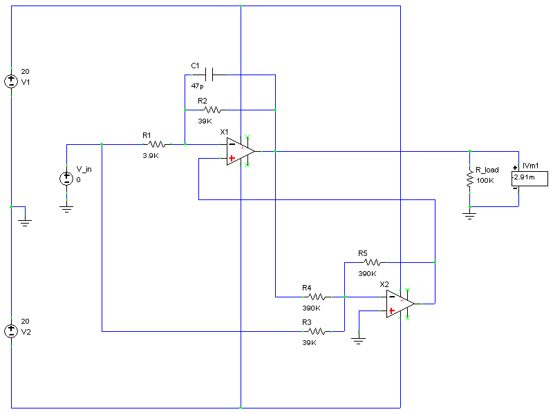
X1 is the main amplifier, with a gain of 10. X2 is the error amplifier, which subtracts the input from 1/10th of the output, leaving only the error. It then amplifies the error and feeds it back to the main amplifier, which then subtracts it from the output, leaving (ideally) a perfect undistorted output. The amount of error correction depends on the gain of X2, with a minimum of 6dB with a gain of 1. In the above circuit the gain is 10, reducing distortion by 26dB With infinite gain, the distortion would theoretically be zero.
In real life things are not quite so ideal unfortunately. There are a few important points here:
- The main amplifier must be slower than the error amp or it will be unstable. In the example circuit this is achieved simply by using a larger than normal feedback capacitor. I would recommend that the gain-bandwidth product of the main amp be smaller than that of the error amp by a factor of the error amp's gain. This ensures not only stability, but also no ringing. It goes without saying that the error amp should be as fast as possible.
- Very high gains for the error amp can cause odd artefacts, even if the main amp is relatively slow enough.
- Certain types of distortion can never be completely corrected, e.g. crossover distortion, which (in some cases at least) is limited by the slew rate of the Vas stage of the main amp.
- The error amp introduces distortions of its own, limiting how low distortion can be made. However, since it has virtually zero power requirements placed upon it, it can be a very low distortion design, perhaps a very linear class-A type. A simple op-amp is sufficient to give substantial benefits though.
Although requiring a second amplifier increases complexity, the distortion and bandwidth enhancements allow for the use of a simpler main amplifier that may otherwise have been discounted because of poor performance. Overall it is possible to have improved performance without extra complexity.
Now for some simulation results. They very closely match measurements obtained from a real-life version. The amplifier under test has deliberately huge odd harmonic distortion added via a couple of diodes, to make it possible to see the results clearly on an oscilloscope.
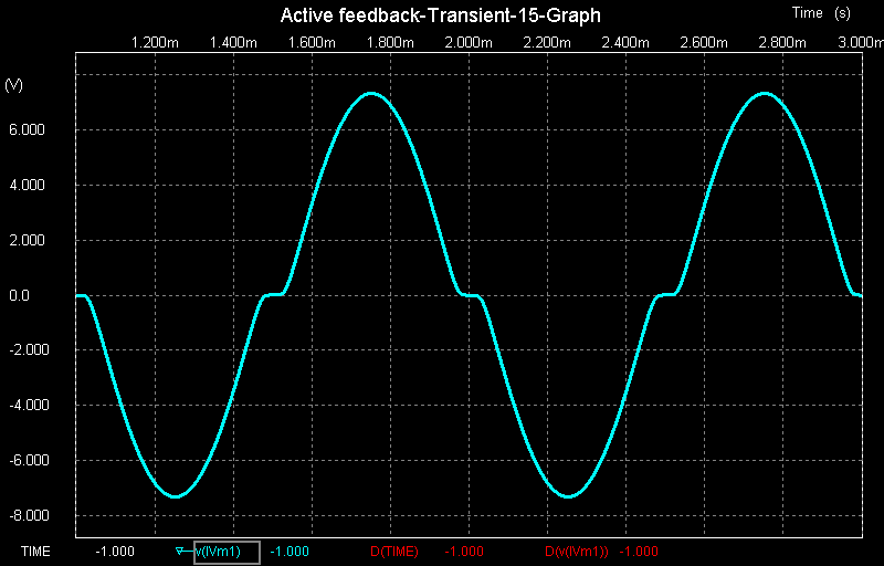
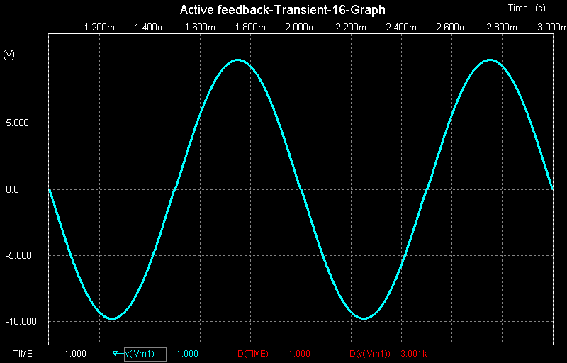
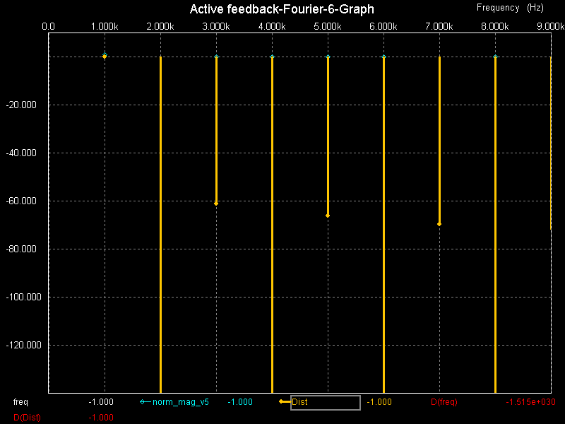
In the first image above you can see the gross distortion that was added. In the second image it's 20dB lower, thanks to the error correction. Next the FFTs of those traces:
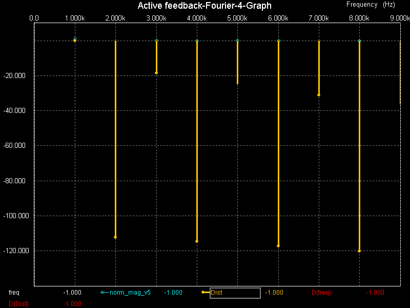
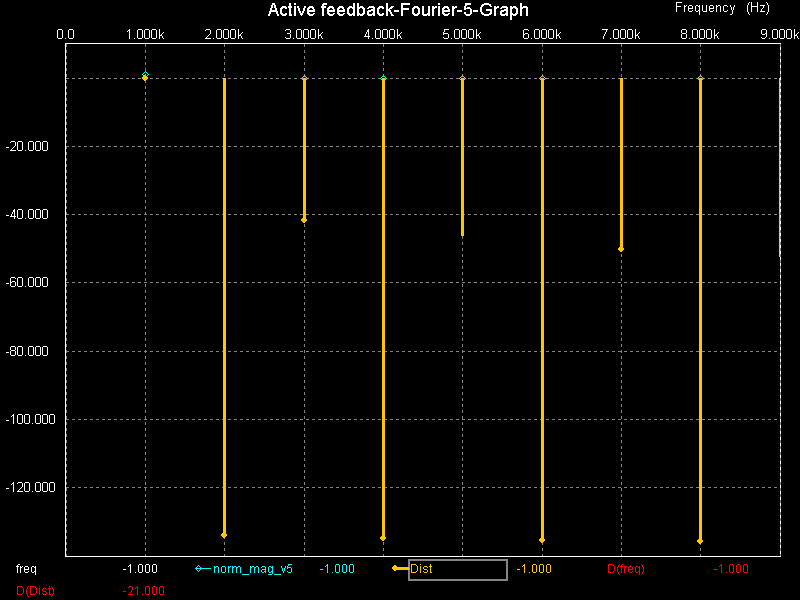
The second image above has a nice 20dB reduction in all harmonic distortion components, exactly as expected. Next more FFT results but with a whopping 40dB of error correction:
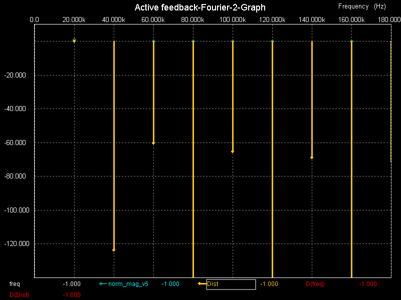
Even such horrible distortion has now be brought under control, demonstrating how an otherwise inadequate amplifier could be brought into useful service by applying this method, or an already good amp could be made superb. Some of the distortion components are off the scale, below -140dB (perhaps I should have chosen larger scales, d'oh!). The second trace shows what happens at 20kHz, where the gain of the main amp is beginning to fall due to the necessarily limited bandwidth. The amount of error correction is reduced somewhat, but only for even harmonics. The effect on odd harmonics remains good until higher frequencies.
More error correction than this is difficult to achieve. In practice it seems that at around 40-60dB of error correction it becomes hard to stabilize the amp, and strange glitches appear. This has been approximately true for all the combinations of amplifiers I have tried thus far.