Amp4 - Subwoofer - Anti-thump
Upon initially constructing the amplifier, I noted that it produced a thump when turned on, and a much larger one when turned off. Previously this was merely an annoyance, but now the amp is hooked up to an efficient horn-loaded speaker, the thump sounds much louder and needs to be dealt with. This circuit does that.
Most anti-thump circuits keep the speaker disconnected for a fixed amount of time when the amp is turned on, then disconnect it immediately when it is turned off. I felt that this was not the most logical way to approach the problem, so I did something different: Thumps occur when the supply rails are too low to allow the amp to control its output voltage. Thus, instead of the method that normal anti-thump circuits use, this one monitors the amp's supply voltages and disconnects the speaker if they are too low.
Schematic
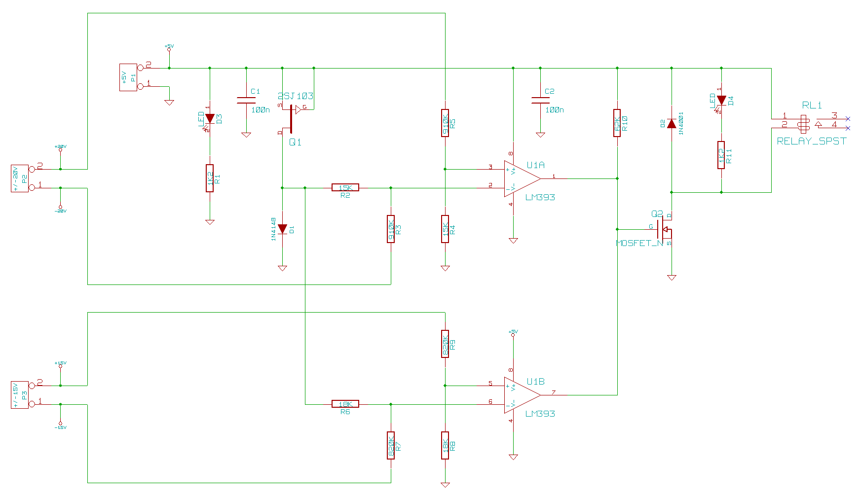
There are two comparators, one of which monitors the amp's two main rails, while the other monitors the output stage's rails. Both operate identically: When the rails are very low, the comparator's inverting input is held up at about 0.6V by the diode D1, while the non-inverting input is at 0V. The output is therefore low. As the rails rise, so the inverting input is pulled down in voltage, while the non-inverting input is pulled up. At some point, the voltage at the non-inverting input exceeds that at the inverting input and the comparator's output stops being pulled low (the comparators have open-collector outputs, so the output doesn't actually go high until both comparators stop pulling it low). When the output goes high, the MOSFET turns on, which turns the relay on, connecting the amp to the speaker. If any of the rails drops below the threshold again, the relay is turned off, disconnecting the speaker.
The exact threshold voltages depend on the voltage reference and the ratios of the resistors. With the values shown, it switches when the main ±20V rails reach 18V and the output stage's ±15V rails reach 14V. In practice, it disconnects the speakers only a couple of seconds after the amp is turned off because the circuit's power supply has only a very small reservoir capacitor and so it can't keep the relay on for very long, even though the amp's supply rails remain high for a while longer. This has no negative effect on the operation of the circuit, so I left it that way.
PCB layout
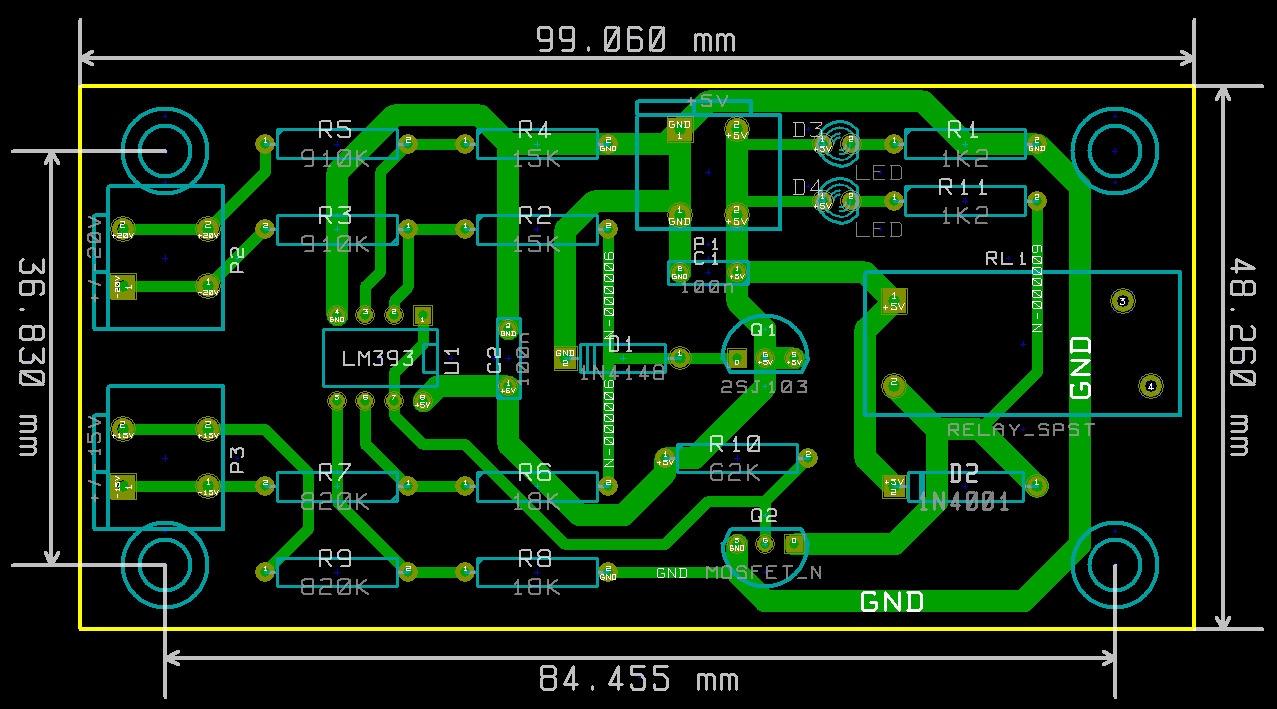
This is a simple circuit, so a single-sided PCB is sufficient. There is nothing noteworthy about the layout.
Finished circuit
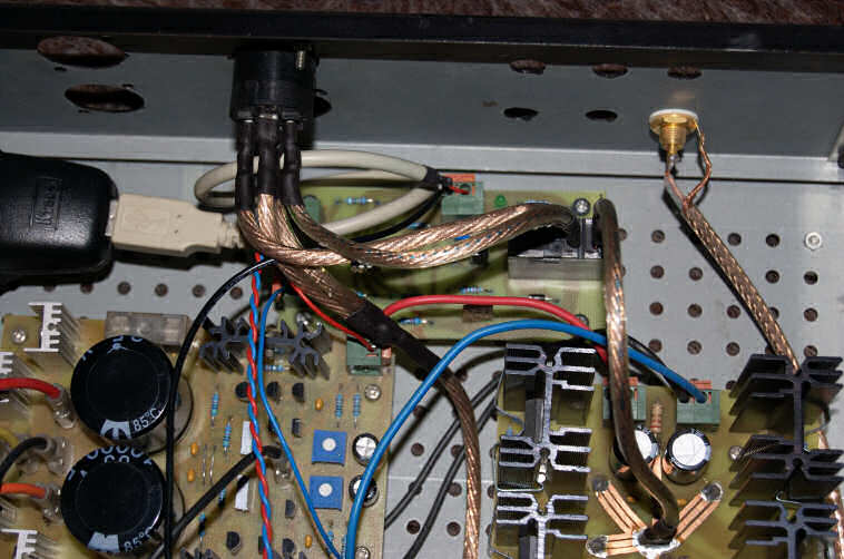
In the above photo you can see the circuit installed, sitting between the amplifier itself on the right and the speaker connector at the top. The circuit works as expected, removing the nasty thumps and leaving only a relay-click in their place. The thing to the left with the USB cable sticking out of it is a USB charger that I used as the power supply for this circuit. These can be found very cheap - cheaper than building a 5V PSU from scratch.