Aluminium and Carbon Fibre ATX Case
For many years my PC has lived within a Cooler Master Praetorian case. It's a good case, but it is too small to fit fans larger than 80mm, or many of the modern large tower CPU heatsinks. I have plenty of space, so I decided to construct something big enough to fit 140mm case fans and the best fanless CPU heatsink I could find.
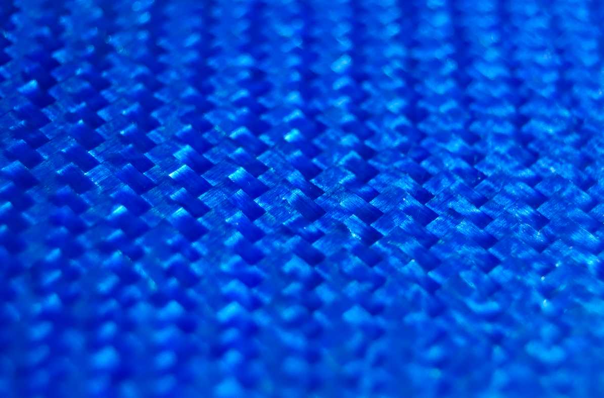
The whole structure of the new case stemmed from my initial desire to make something from coloured carbon fibre panels (actually the colour comes from a layer of metallized glass fibre on top of the carbon fibre). Practically, carbon fibre has few properties that are helpful for a computer case (it has better damping than aluminium, so it should be a tiny bit quieter), but many that are unhelpful (high price, poor electrical conductivity), so the choice was purely because I like the way it looks.
Planning
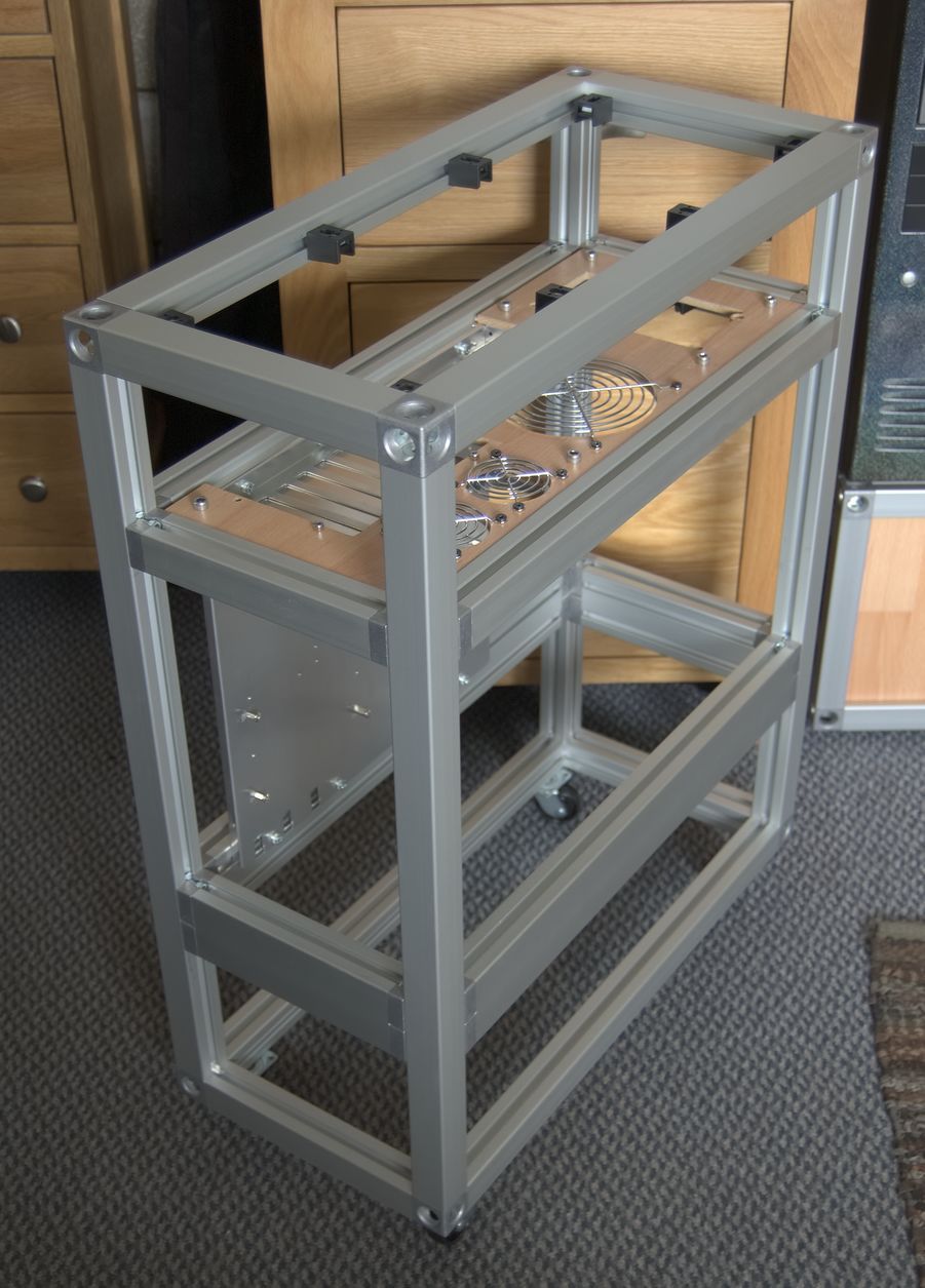
I spent quite a while pondering possible methods of construction that would allow the panels to be joined neatly without too much work, and allowing the PC's components to be mounted securely inside. Eventually I decided that aluminium extrusions would be the best solution. There are a few common standards for the stuff, and it's currently popular for making DIY 3D printers because it's very rigid and easy to mount other parts to. To verify its suitability for my purposes, I ordered a small quantity and used it to make a stand for my file server. It worked well for that, so I moved on to designing the case.
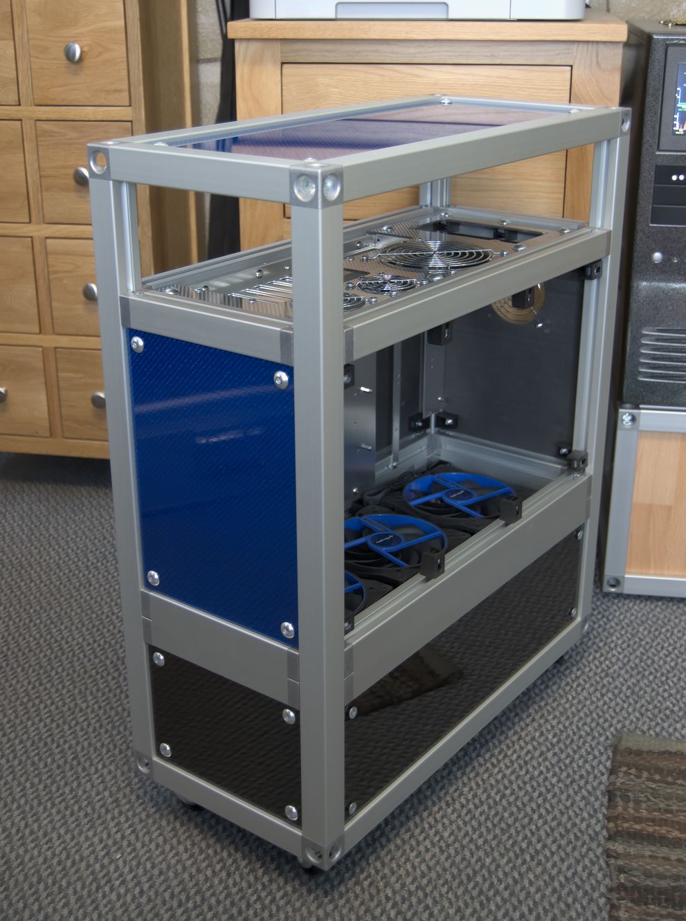
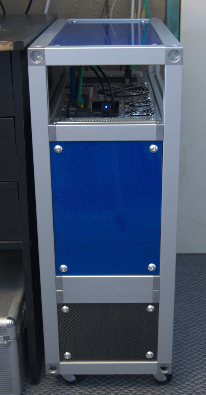
I prefer to use positive pressure (only intake fans) because it makes it much easier to control dust. One disadvantage of this is that the typical location of intake fans at the front of the case puts them closer to the user, and thus they sound louder. This can be addressed by moving them to the bottom of the case, but then the airflow is completely blocked by the graphics card. Airflow can be restored by rotating the motherboard 90°, which is an idea that has been around for a while, and there have even been commercially produced cases with such a layout, most notably the SilverStone Raven. Another advantage of this style is that the rear connectors become easily accessible at the top of the case. A disadvantage is that those same connectors become vulnerable to dust. I decided to put a solid cover over them to stop dust falling directly into the connectors, and hopefully the constant flow of air will prevent any dust from falling in around the sides. I also wanted to integrate a stand into the case, to lift the intake fans far enough off the ground that they can suck in air freely without pulling dust in with it.
To fit 140mm fans, leave room under the cover to reach in to the rear panel connectors, and to put the fans a reasonable distance off the ground, the external dimensions ended up being 250mm wide x 660mm high x 560mm deep. That's pretty big, especially considering that PCs have been steadily decreasing in size over the years, but it's still smaller than some currently available ATX cases. Some space was saved by the omission of drive bays, which aren't needed now that optical drives are virtually obsolete, and I have no HDDs, only SSDs which are small enough that they can be attached to any convenient surface.
Construction
I bought the aluminium extrusions from KJN, who will cut it to length for a small fee, which means that there wasn't a lot of work required to assemble the frame beyond bolting the parts together. I also purchased a motherboard tray, which are handily available separately from Lian Li (they sell a lot of case parts separately, which is great for DIY) and bolted it to the frame.
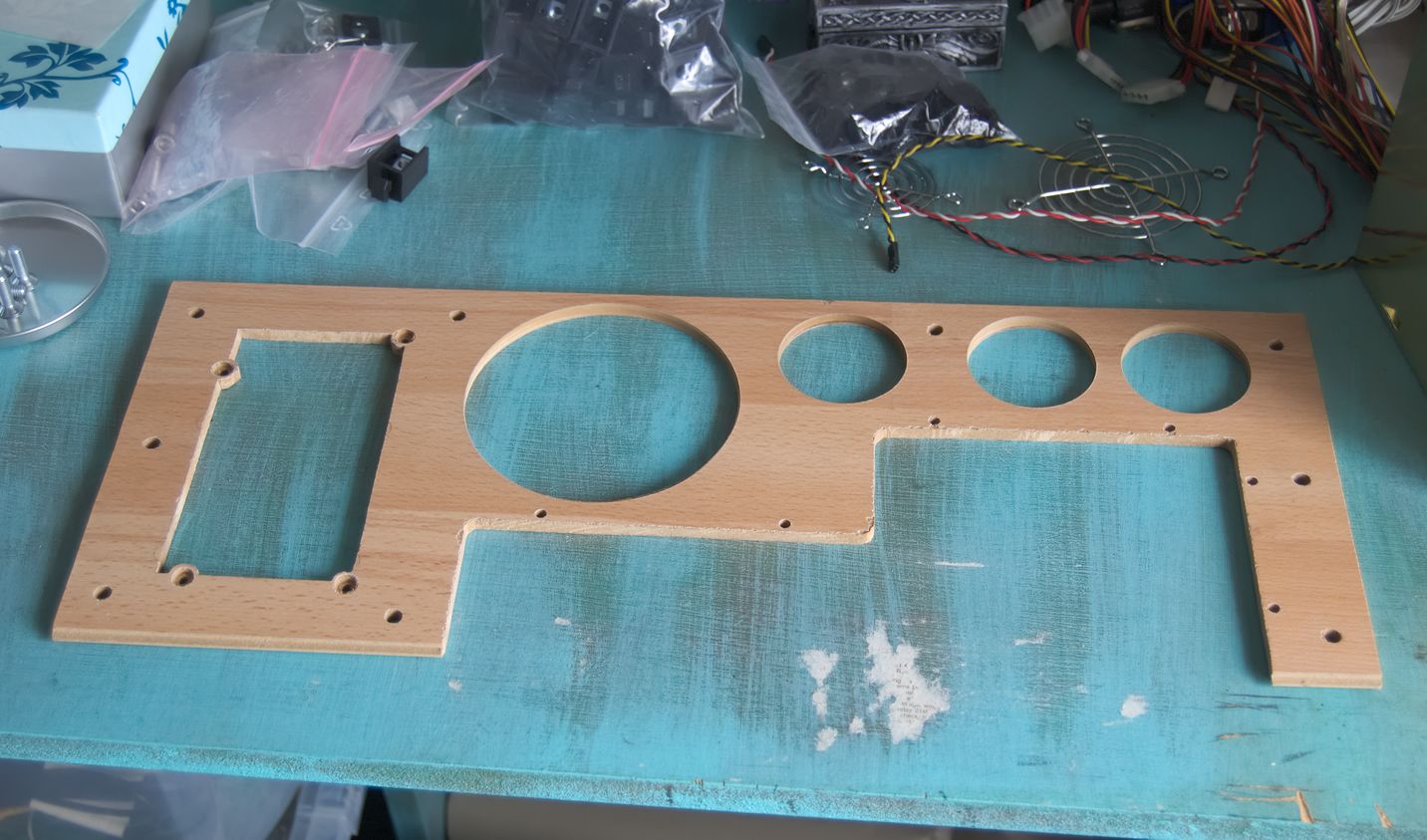
In order to perfect the layout of the rear panel, and to give me some practice at cutting before trying it on the expensive carbon fibre, I created a couple of iterations of prototype panels from bits of spare laminate flooring.
The carbon fibre panels were made by Composite Envisions, who sell all manner of decorative carbon and other fibres. I had them cut the panels to size for me, as they needed to be quite accurately sized to fit tightly, and I don't really have the equipment to cut things that accurately (a jigsaw and a straight-edge only go so far). The panels are 3mm thick, which is what I estimated would be required to hold the weight of a PSU without flexing. Most of the other panels could have been much thinner, but I decided it would be simpler to use the same thickness for everything.
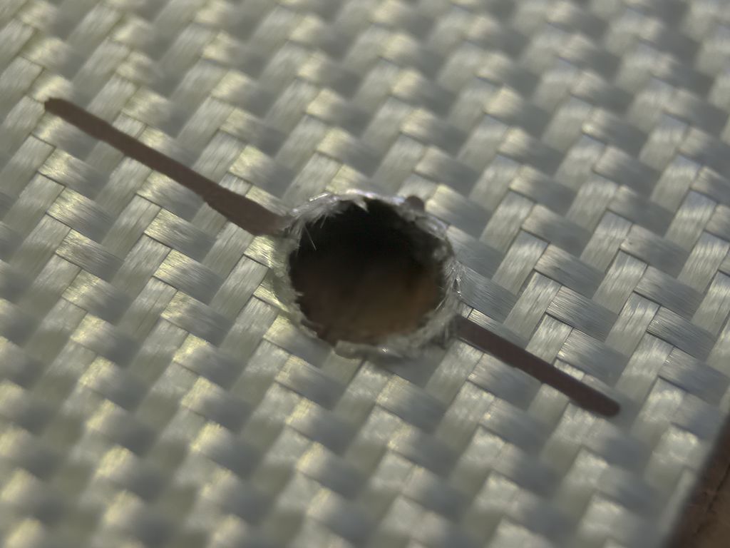
There was still a bit of cutting and drilling to be done, and carbon fibre is particularly difficult to work with. Partly because it is a mixture of hard fibres and soft plastic, which makes it difficult to cut cleanly, and partly because it is very abrasive, which wears out tools very quickly. The dust is also electrically conductive, which can cause problems with power tools if it gets inside.
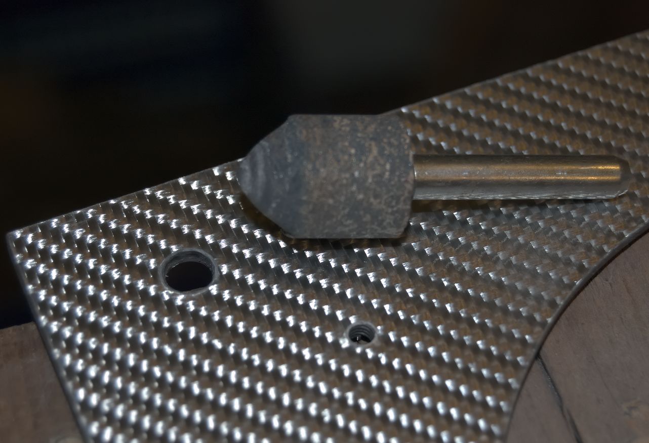
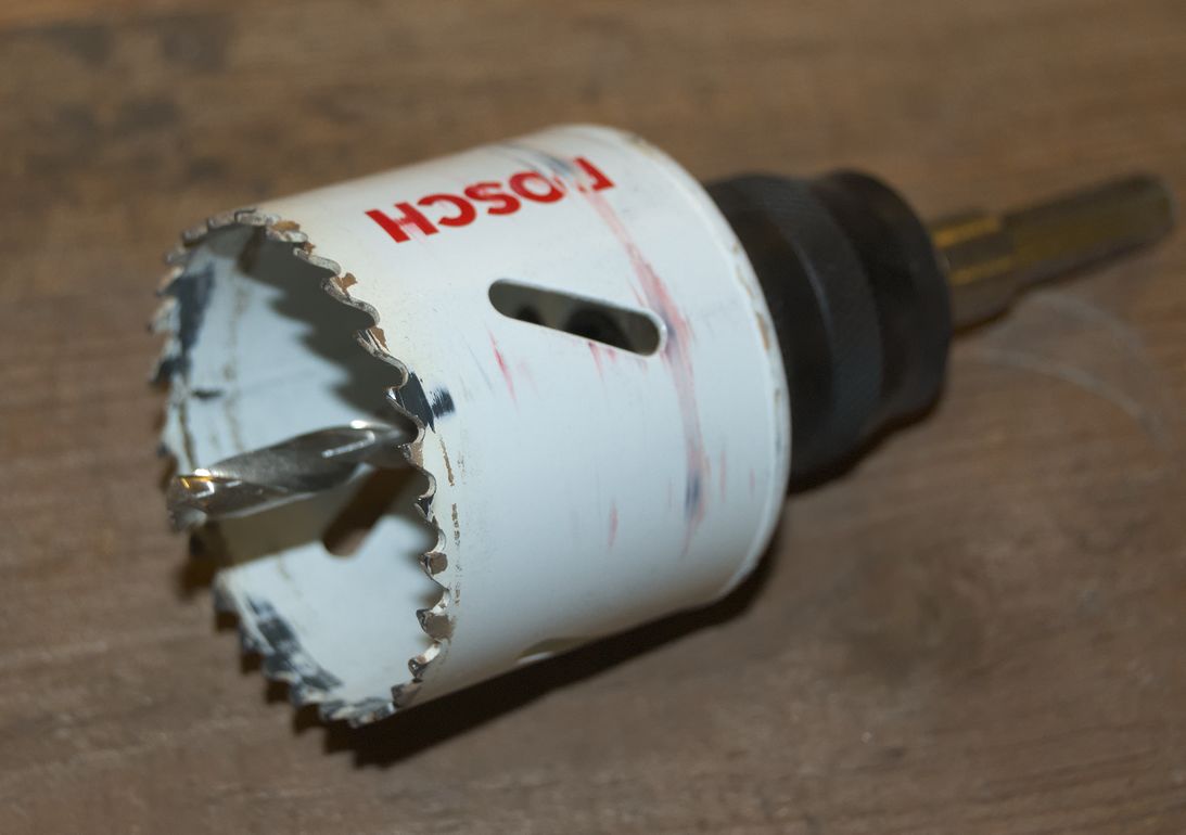
For drilling, I would normally use brad point drill bits, as they cut the neatest holes. However they are generally only available made from HSS, which will only last a few holes before being blunted by the carbon, and I had too many holes to drill to put up with that. Bits made of very hard materials like tungsten carbide or diamond are best, but very expensive. I compromised by getting some cobalt steel bits, which are in-between in hardness. The cobalt bits lasted longer than HSS, but didn't cut very neat holes, so I tidied up the edges with a grinding bit. For larger holes I already had some cobalt hole saws, which cut surprisingly neat holes.
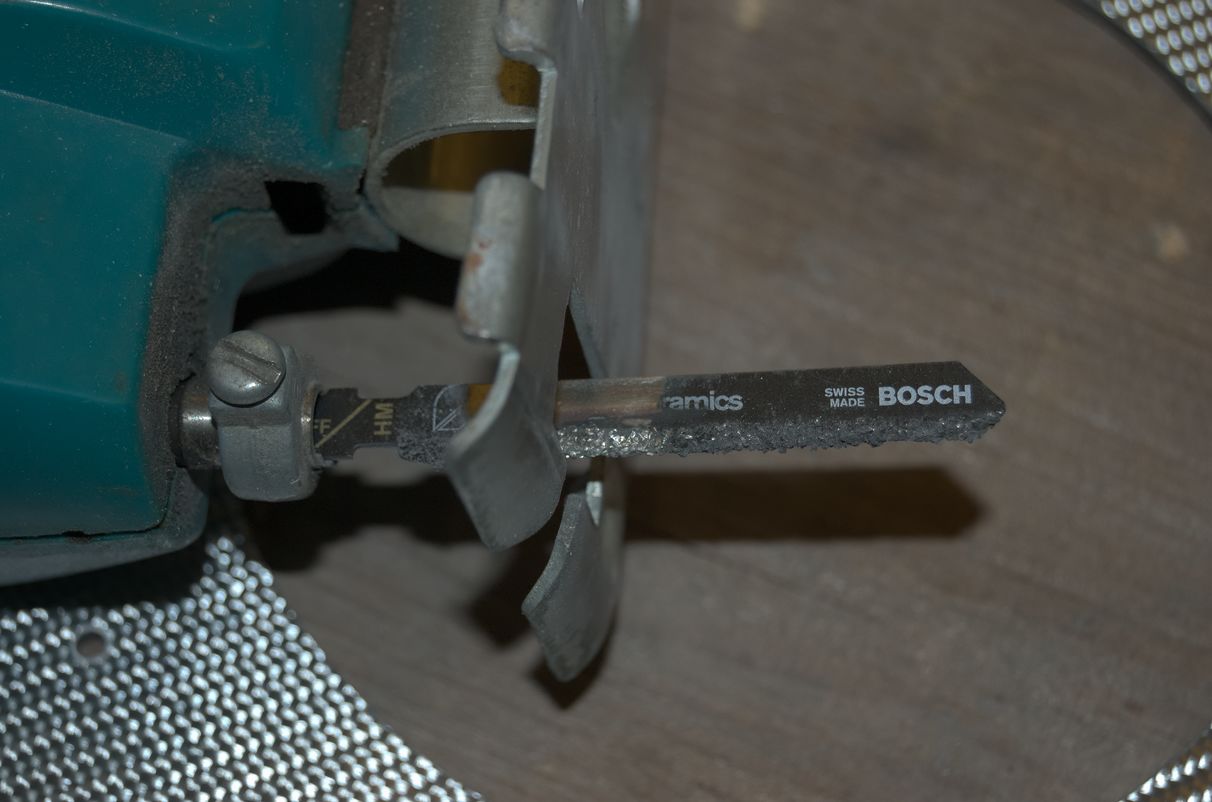
For everything else I used a jigsaw with a tungsten carbide grit blade. These cut carbon fibre much more cleanly than normal blades with teeth, and are easier to turn corners with because they can cut sideways a little. I used a coarse grit blade; a fine grit blade would cut slightly cleaner, but a lot slower.
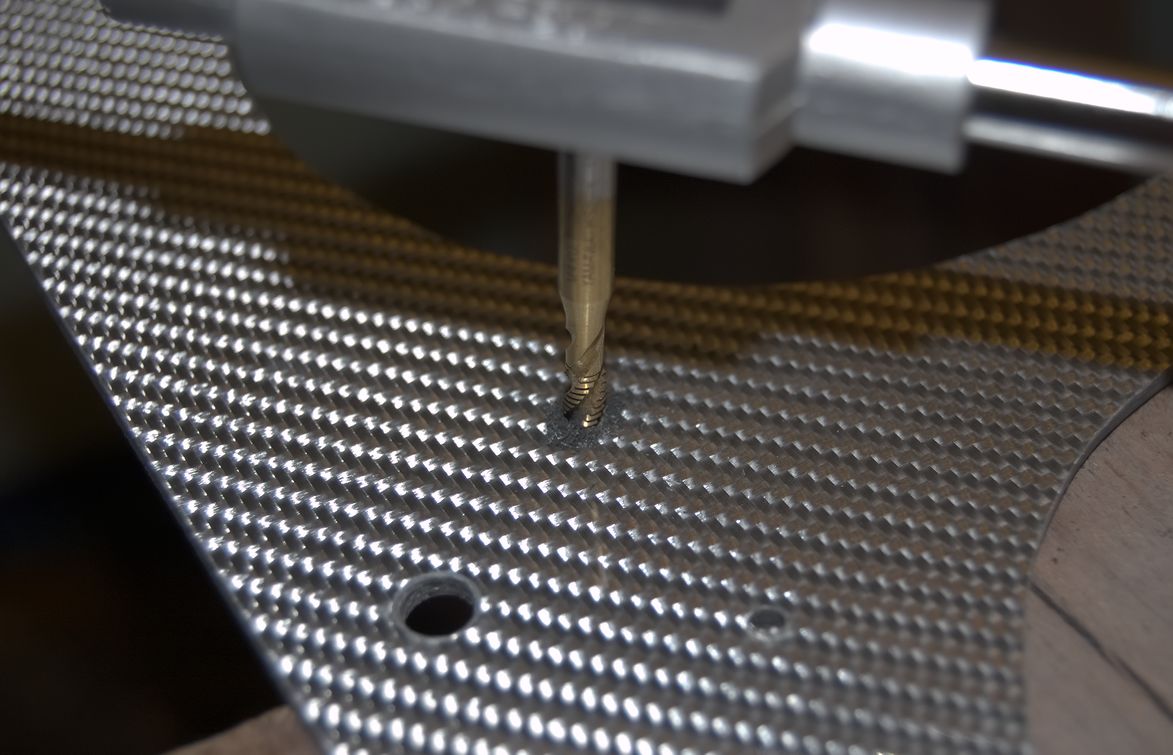
The last thing that needed to be done to the panels was to tap a few holes for attaching the fan grills. Carbon fibre doesn't hold a thread very well, but it's good enough for applications like this that don't need much strength.
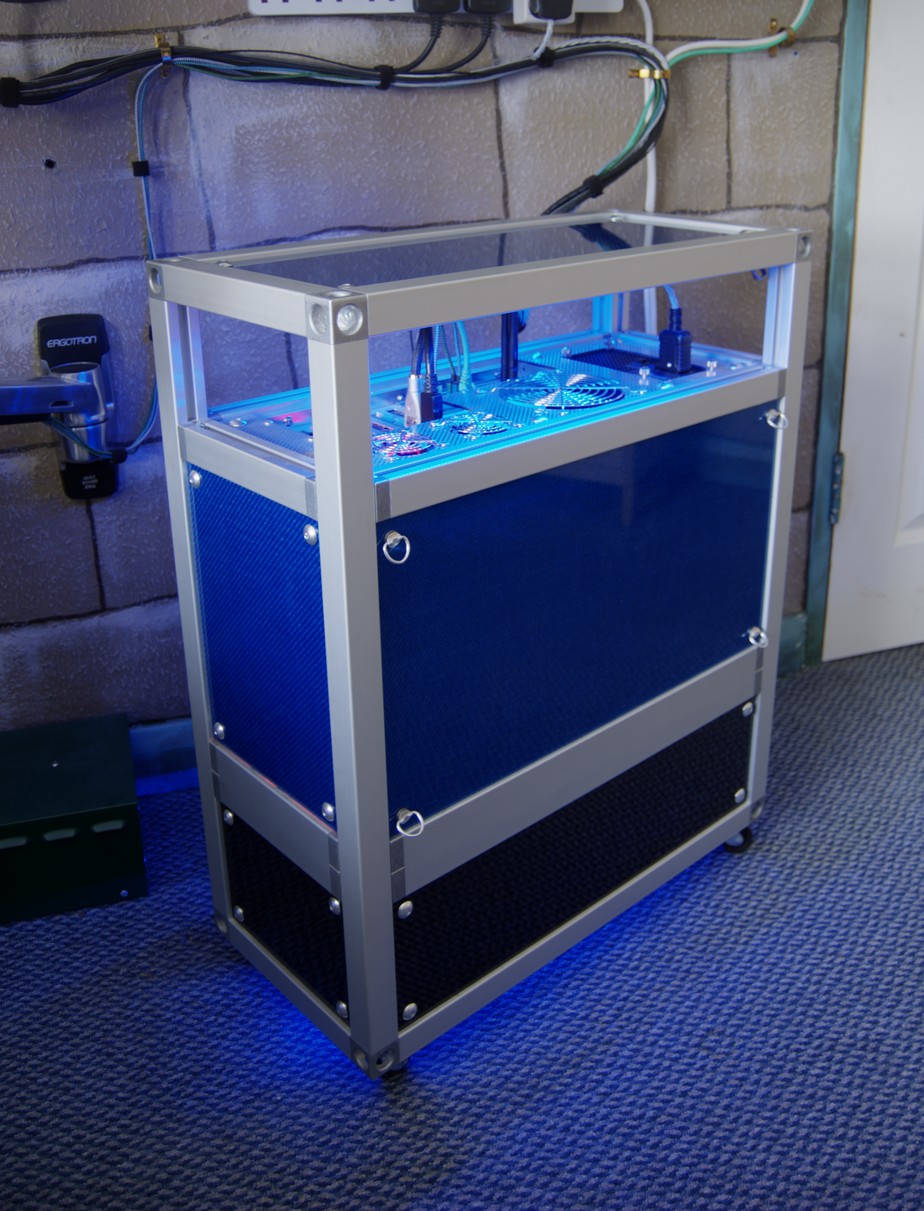
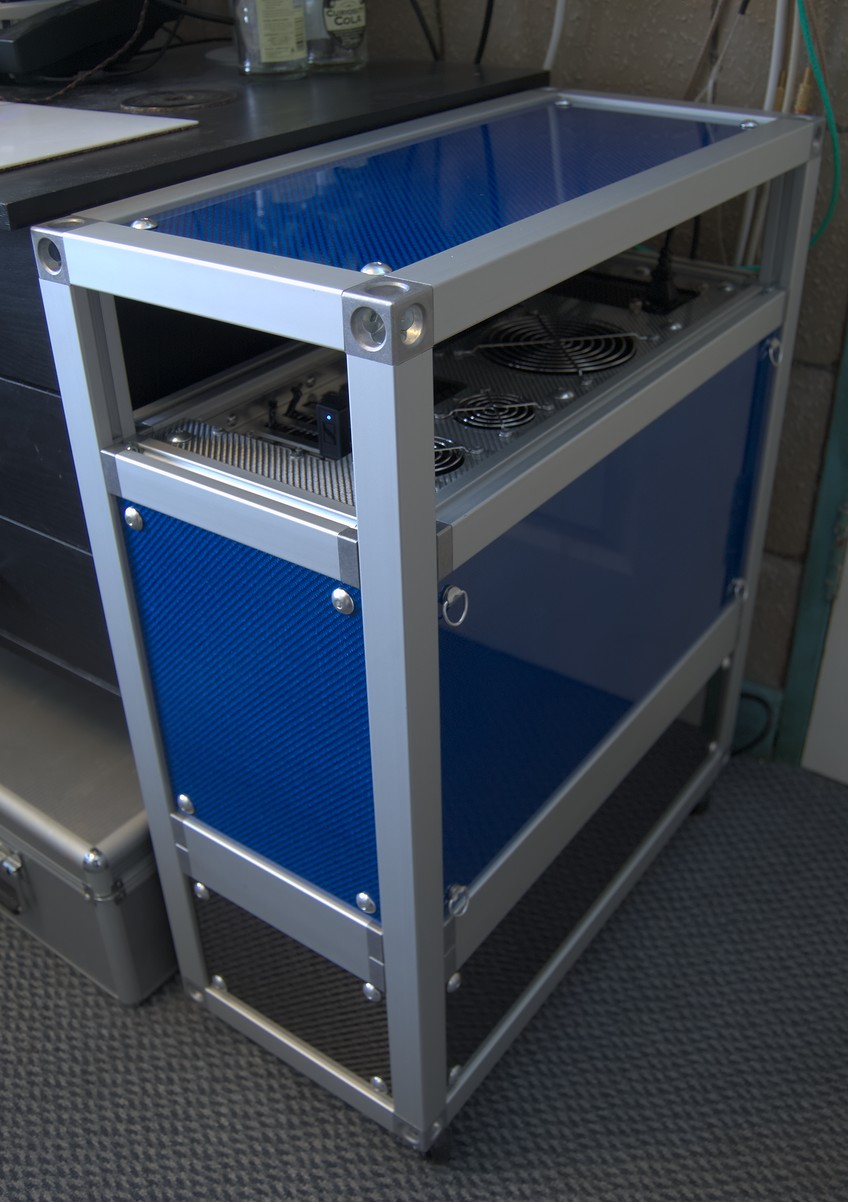
With the unpleasant experience of carbon fibre dust (it's nasty stuff - make sure you wear a mask when working with it) over and done with, I attached the panels, and the case started to look like a case.
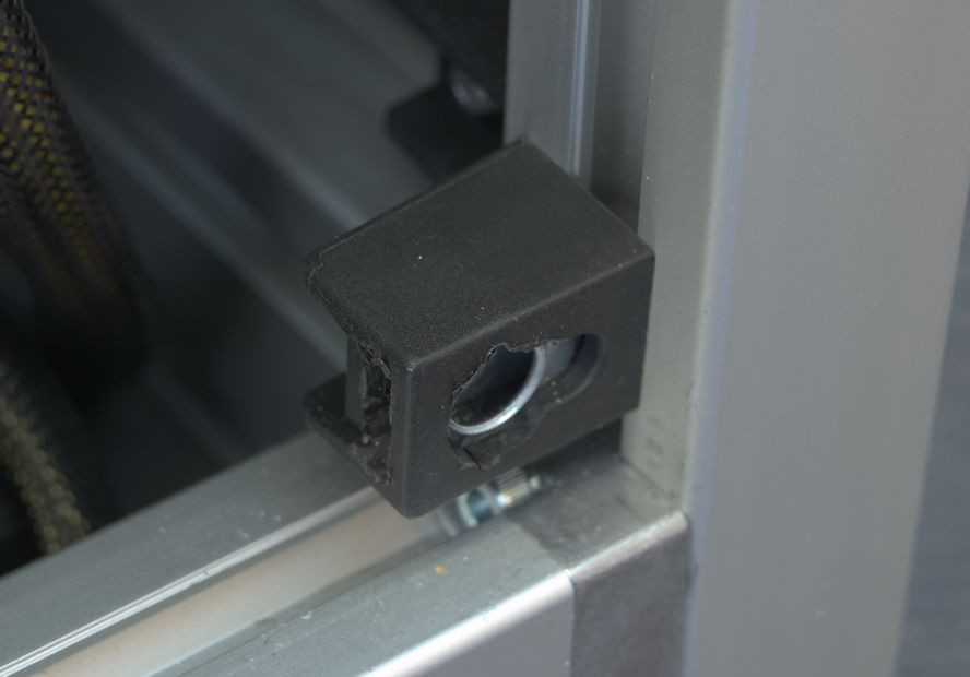
The black plastic blocks around the inside edges of the frame are what the panels bolt to. The blocks are non-conductive, so the panels are not electrically connected to the frame and will provide very little electromagnetic shielding, allowing RF interference emitted by the PC to escape. Not ideal, but I don't have to pass an EMC test, so I'll leave it as it is.
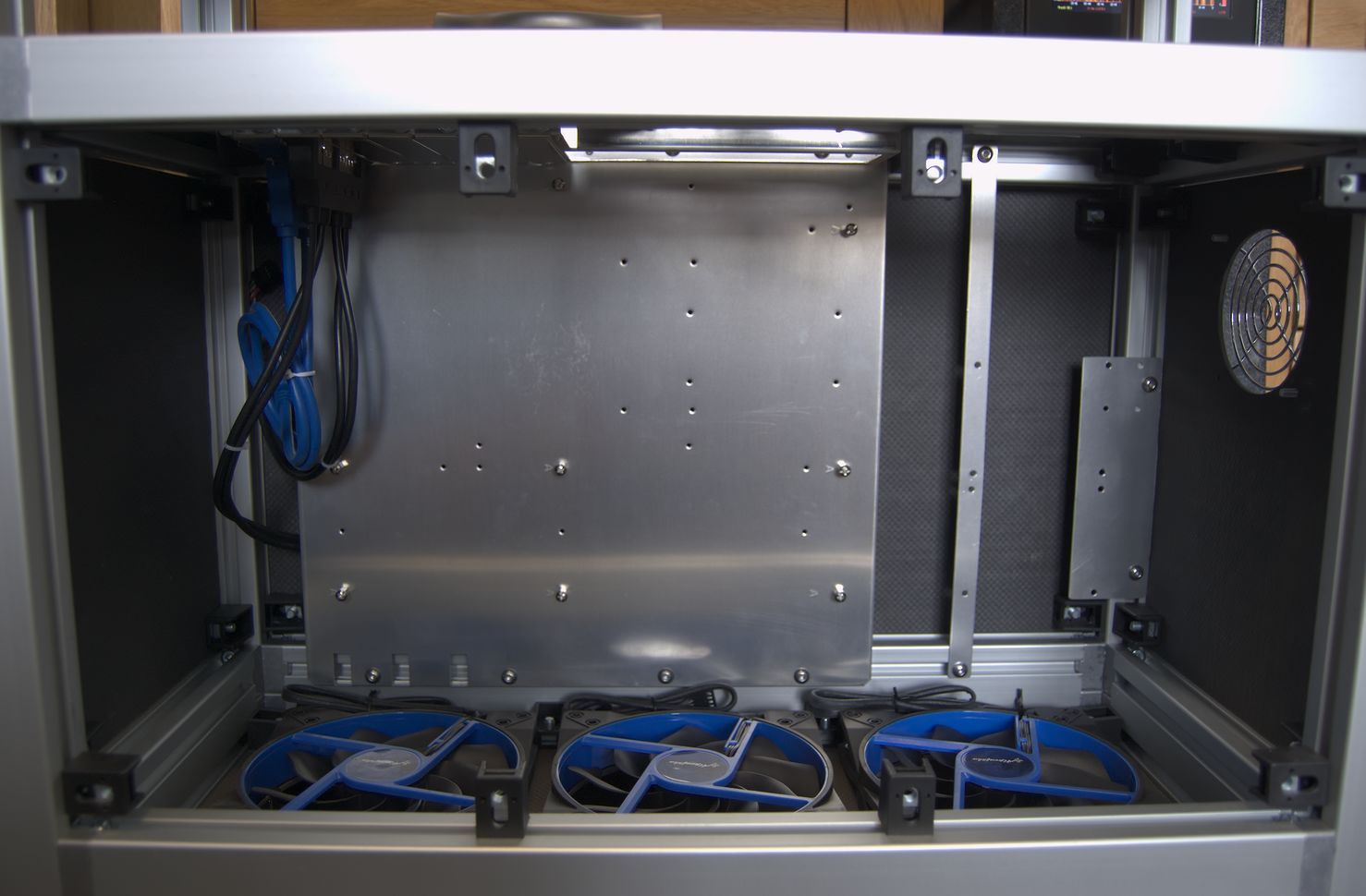
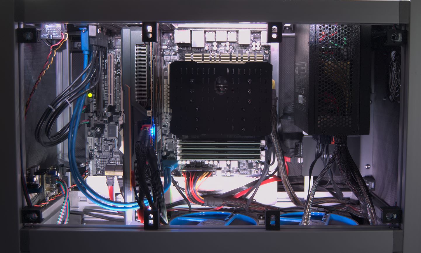
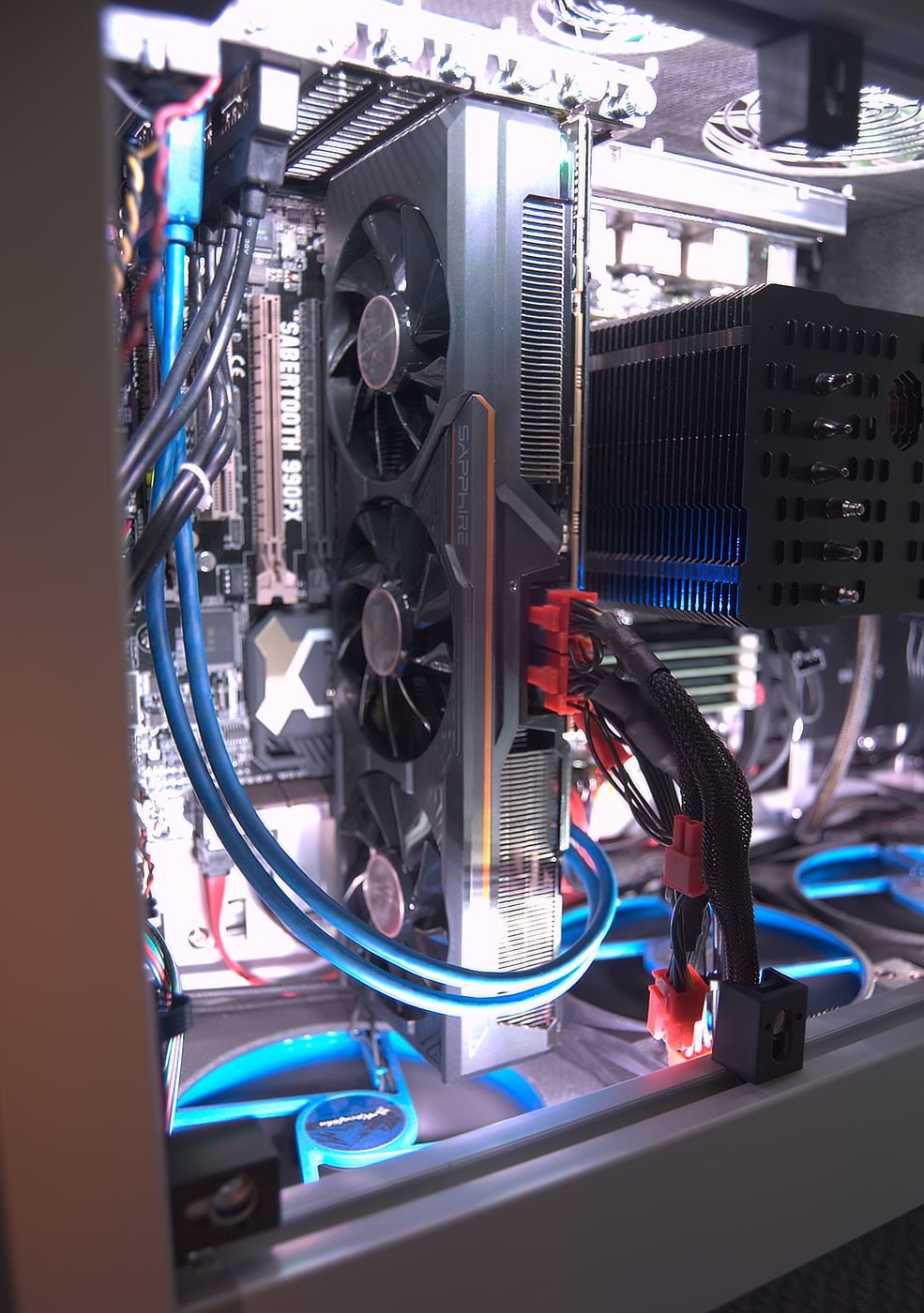
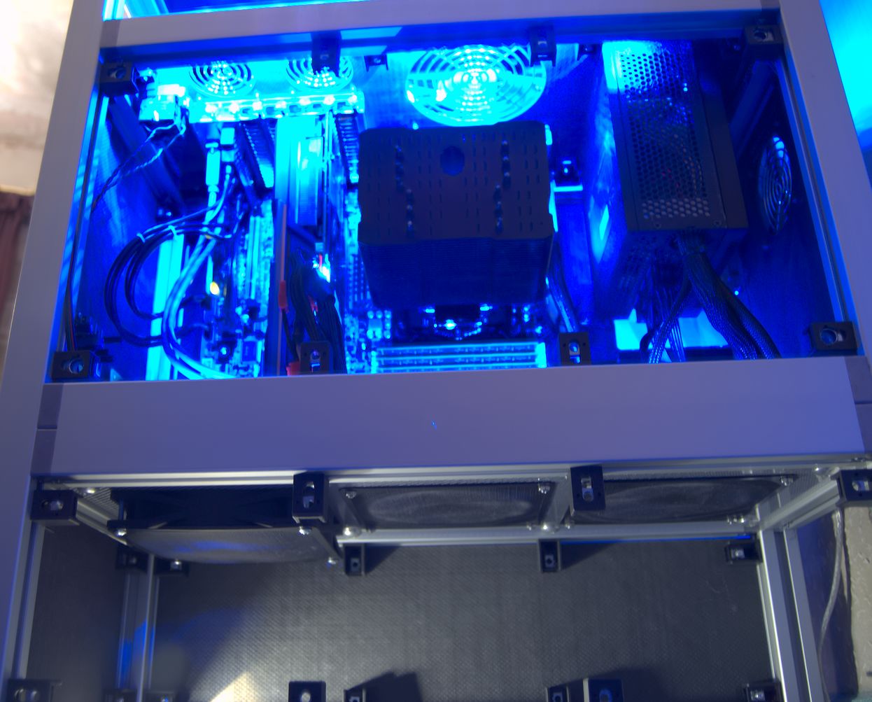
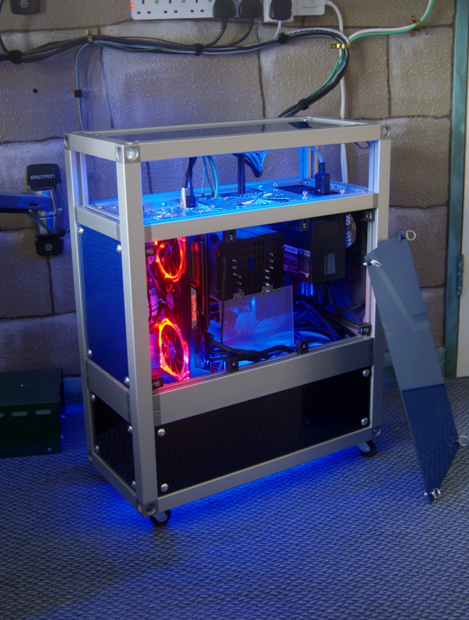
There is 300mm between the PCI slots and fans - more than enough to fit my graphics card. Some cards are bigger than 300mm, but could be accommodated by moving the fans down to the other side of the panel that they are screwed to, yielding an extra 25mm. This is not quite enough to fit my Sapphire Fury Tri-X, so I had to move one fan underneath the panel. The odd bits of aluminium to the right of the motherboard tray are for mounting my SSDs. The grill on the right is to allow air to flow past the far side of the PSU (which is important because I have a passive PSU which relies on its external surface as a heatsink). The fans are Alpenföhn 140mm "Wing Boost 2 Plus", which I chose because they are PWM fans with a very low minimum speed (300rpm), and they're blue. I plan to put a dust filter before the fans, but I have yet to decide the best way of doing so. I put some basic aluminium mesh filters under the fans to keep the dust out.
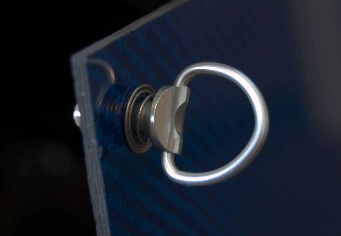
So that I don't need to get an allen key every time I want to access the inside, I attached the side panels with ¼-turn quick-releases instead of bolts. I got them (and all the shiny aluminium bolts I used for the other panels too) from Pro-Bolt.
Being constructed from modern lightweight materials, this must be a light case, right? Wrong! It's massively overbuilt and weighs 14.7kg; I could probably literally smack it with a sledgehammer and not seriously damage it. It is nonetheless easy to move around thanks to the castors and convenient gap all around the cover to use as a handle.
Installation And Testing
Aside from a year-or-so's worth of dust that needed to be dislodged, it was straightforward to transfer the components of my PC to their new abode. The only problem was a slight flaw in the case design - the PCI slot screws are obstructed by the frame, making it hard to use a screwdriver on them. This is only a minor inconvenience though, as they are thumbscrews that can be done up by hand.
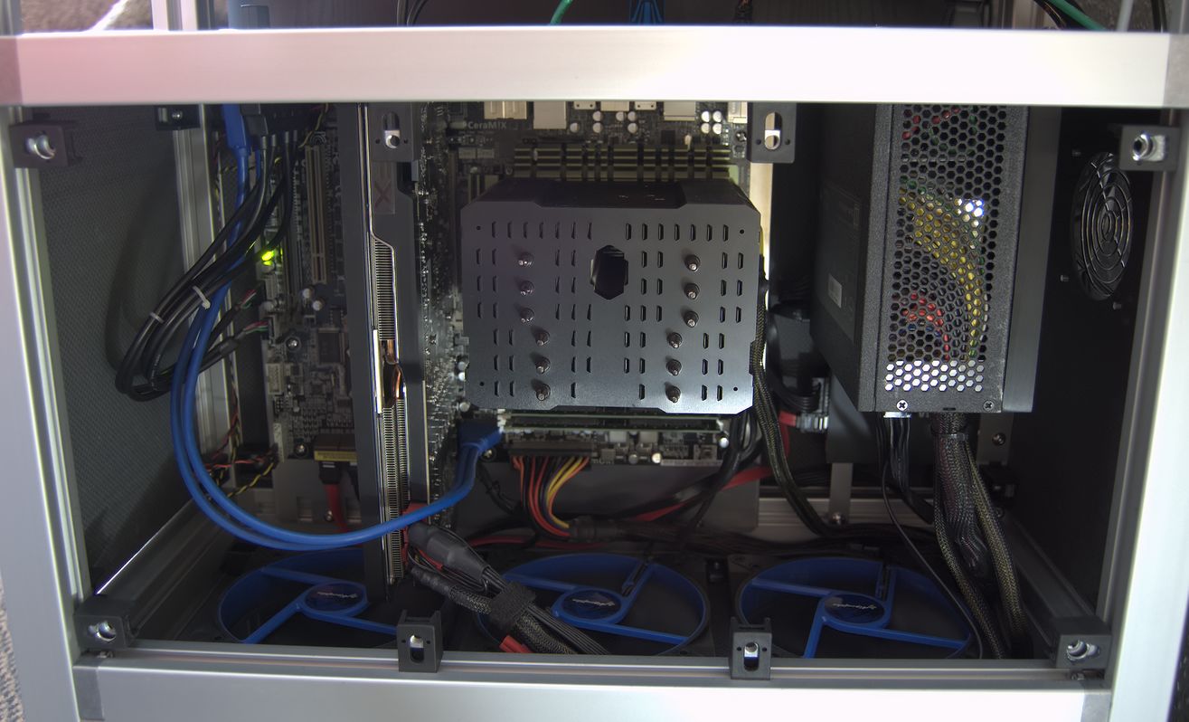
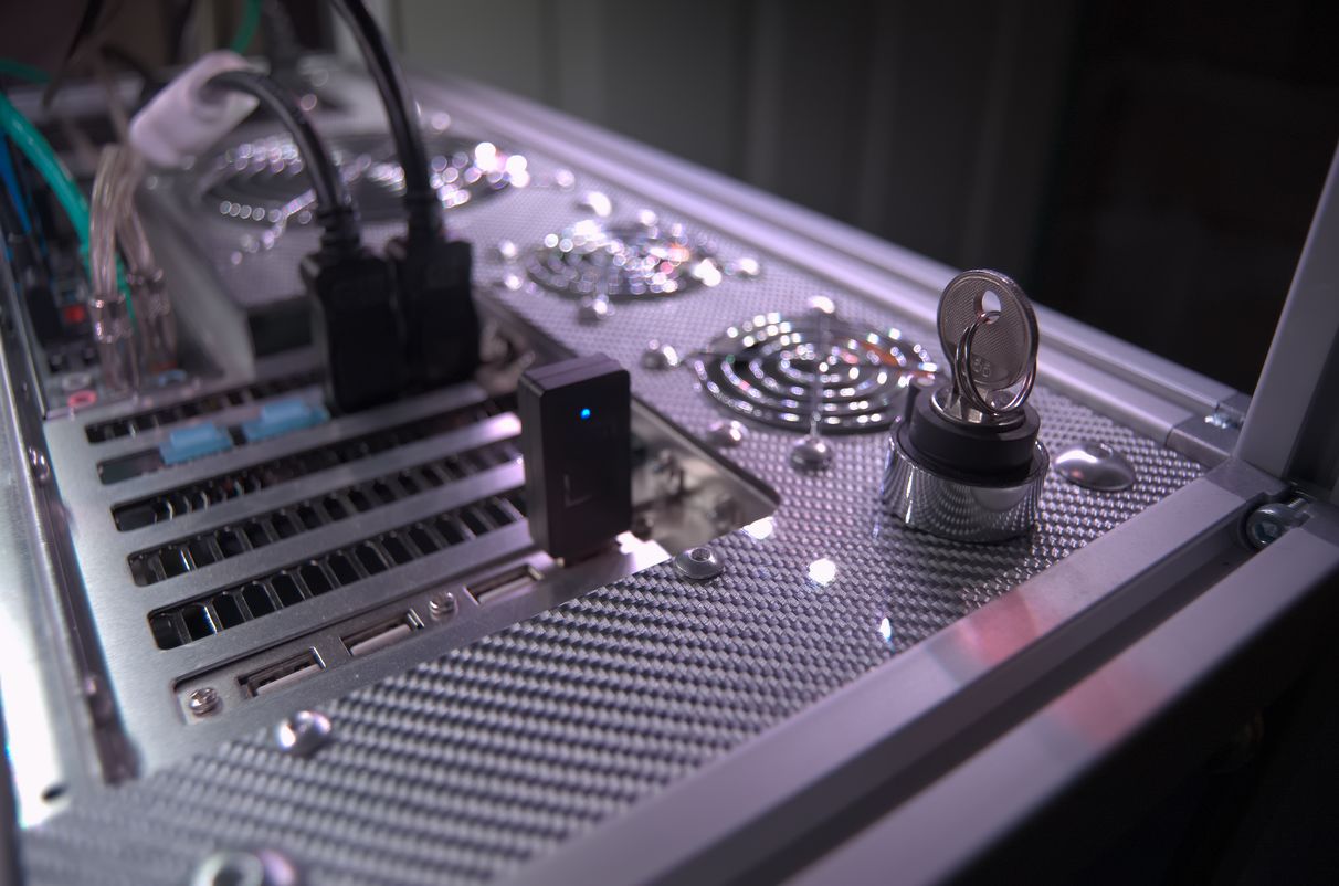
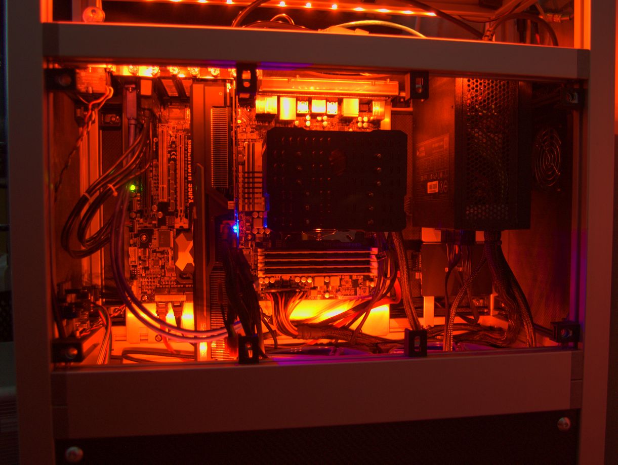
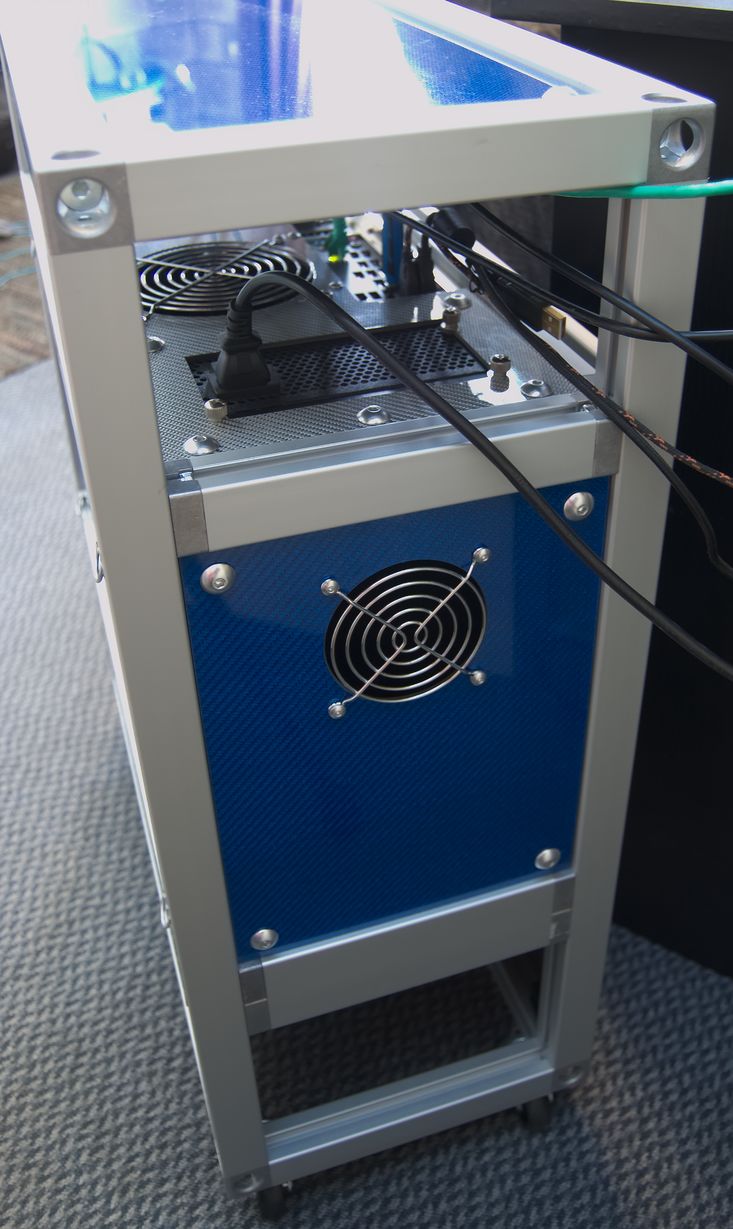
It's not immediately obvious from the picture, but the PSU faces the opposite way to how it would in a normal case. This places its external heatsink (where the fan would be on a fan-cooled PSU) facing away from the CPU, towards the grill on the rear of the case.
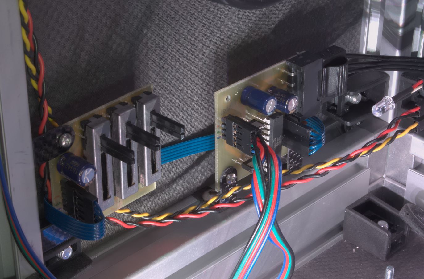
I am using SpeedFan to control the fans, with the fan on the left linked to GPU temperature, the middle fan linked to CPU temperature, and the fan on the right fixed at minimum speed (which I achieved by physically shorting its PWM input to ground, since my motherboard does not have enough controllable outputs to control all the fans separately in software), as the PSU needs little cooling (in fact the third fan could be removed entirely with no ill effect). The fans are not the quietest I have heard, making a distinct clicking sound at low speeds (which is disappointingly common for PWM fans), but they are quiet enough that I don't notice them if I'm not listening, which is quieter than the 80mm fans in my old case (which ran at about 800rpm at idle).
The heatsink is the strangely named "Macho Zero" from Thermalright. It's one of very few heatsinks designed to work without a fan mounted directly to it, which requires that the fins be spaced further apart than usual because a distant case fan can't apply enough pressure to force air through closely-spaced fins. I'm pretty pleased with how well it works - running Intel Burn Test to fully load the CPU (I estimate this to be about 60W of heat) with all three fans kept at their minimum speed (nominally 300rpm, but actually about 340rpm for mine), the CPU eventually reaches a maximum of around 65°C (with an ambient temperature of 20°C).
The GPU is not so easy to keep cool. Running FurMark to push its power output as high as possible (I estimate 240W) and manually adjusting fan speeds, I ended up with the fans on the GPU itself at about 2900rpm and the associated case fan at 700rpm to keep the GPU at my conservative target temperature of 70°C. At these speeds the GPU fans are quite loud, and the case fan is definitely audible. The speed of the case fan has a much smaller effect on the temperature than the GPU fans (which is expected, because blowing more air towards the GPU fans doesn't help if they are already sucking air in as fast as they can). I considered buying a fanless heatsink for the GPU, as I did for the CPU, but there are none available rated to cope with that much heat. A larger fan-cooled heatsink would probably help a lot though, to take advantage of the huge volume of air pushed by the case fans.
I originally planned to put power and reset switches on the front panel, but I decided that it would be better not to do anything to interrupt its texture. I will probably mount some reed switches behind the panel so I can operate them from outside (using a magnet) without anything being visible externally. For the moment I just have some microswitches wired up and poking through a vent in the rear panel. I ended up fitting a key switch, as this is 100% cat resistant (I have had cat-induced power-off incidents before). It was quite hard to find a two-pole momentary switch with centre off (turn one way for power, the other for reset).
This is certainly not the most cost-effective case possible; even if I hadn't used carbon fibre, the aluminium extrusions are not cheap. Still, it did result in a case that was very easy to construct, works very well, and looks very nice.