Laser Blinkenlights
This project is a replacement for a device I made many years ago to decorate someone else's PC with LEDs that flashed based on CPU usage. The original stopped working some time ago after a Windows upgrade, probably due to driver problems for the USB to serial adapter. Drivers for those things are a constant source of problems, so I thought I would replace it with something implemented completely in hardware, so it can't become broken due to software changes. To make it a bit different to last time, I used lasers instead of LEDs, because lasers are cool.
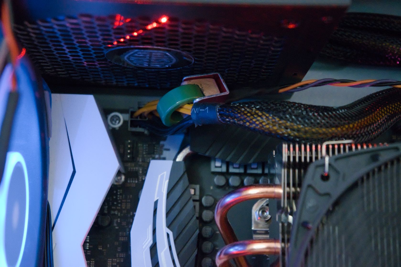
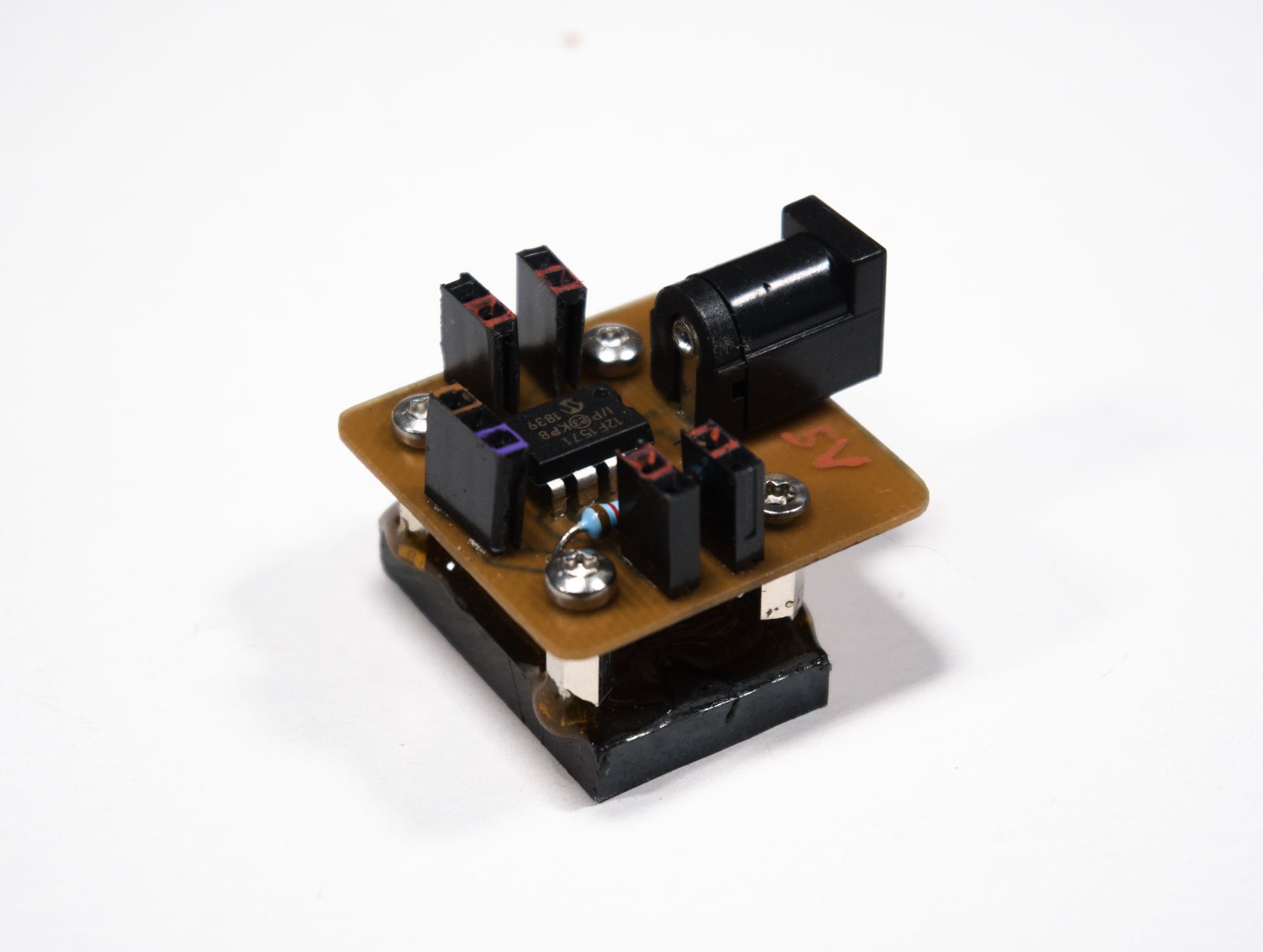
It's not possible to directly measure CPU usage externally, but it can be inferred from power consumption, which is proportional to current consumption, which can be easily measured thanks to the modern ATX form factor requiring the CPU to have its own power cable. To make it as non-invasive as possible, I used a Hall-effect sensor to measure current, which it does indirectly via the magnetic field around a cable generated by the current it carries. The particular sensor I used is a DRV5056-A1, which has decent sensitivity and is unipolar (it only needs to measure current in one direction).
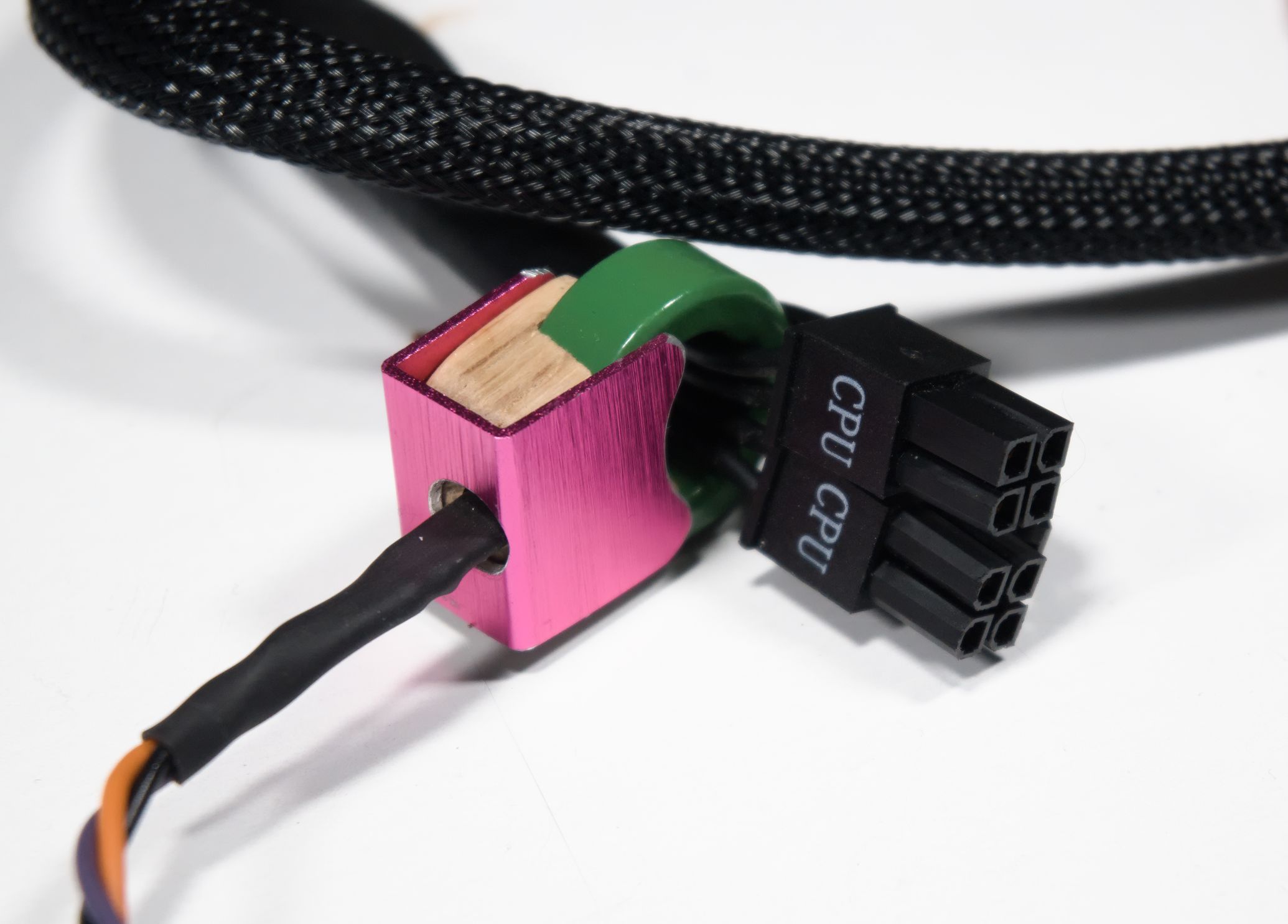
The magnetic field is weak, so it needs to be concentrated onto the sensor by surrounding the cable with a magnetic core. I don't know exactly what sort of core the one I used is - it's just the highest permeability core of suitable size I could find in my parts drawer, with a slot cut in it to fit the sensor into. Given the metallic appearance of the bit that was cut, it might be powdered iron or other metals, but not ferrite.
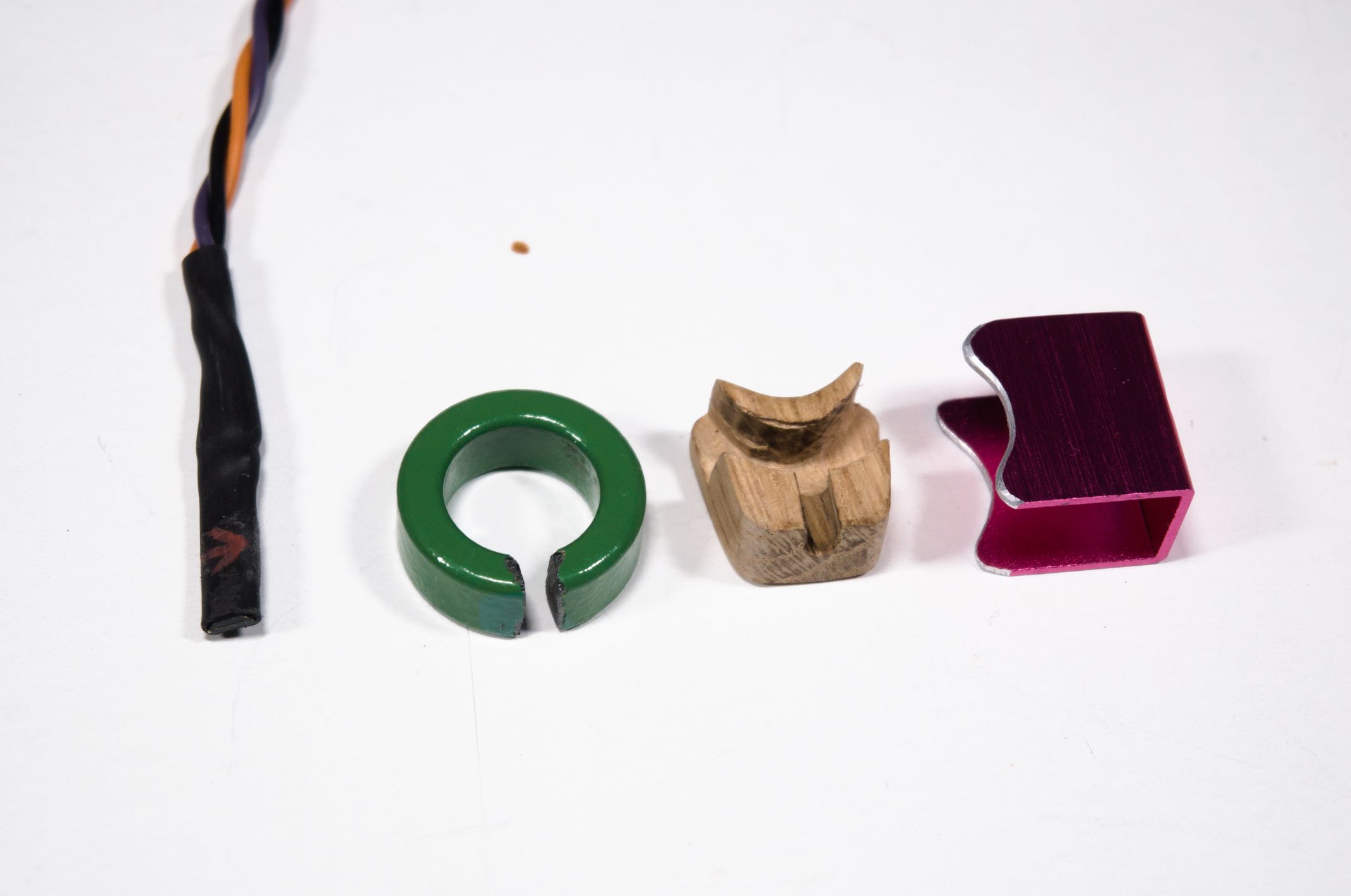
To hold the sensor in the right position relative to the core, I carved a little bit of wood. I used oak for this, as it's strong enough to not split when cut into thin shapes. This is then clamped to the core by a piece of aluminium that I cut out of an old external hard drive enclosure.
The sensor outputs a voltage proportional to the magnetic field strength, which is itself proportional to the current. This is then read by a microcontroller, which turns it into a pattern to blink some lasers.


The microcontroller, a PIC12F1571, reads the output from the sensor periodically, and adds the value to a running total, which is effectively the total amount of energy used by the CPU. This is then converted into a balanced Gray code, which is output to the lasers. The Gray code has no real meaning - it's just to look nice. Every time the recorded energy use increases enough, the output pattern changes. Thus the rate that the lasers flash represents the amount of power the CPU is using. It's self-calibrating, automatically scaling the output according to the peak current that it has measured since powering up. This allows it to work with CPUs of different power consumption without having to change anything.
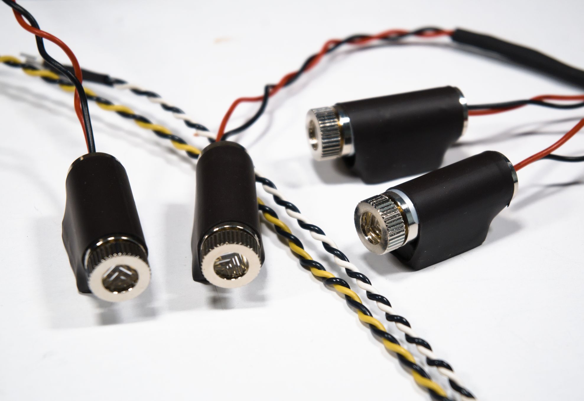
For the lasers, I got four cheap laser diode modules. These conveniently have built-in linear constant-current drivers, and the metal casing provides enough heatsinking that they can run continuously. They produce a cross-shaped pattern rather than the dot you might expect from a laser. This spreads the light out over a larger area, making it more visible.
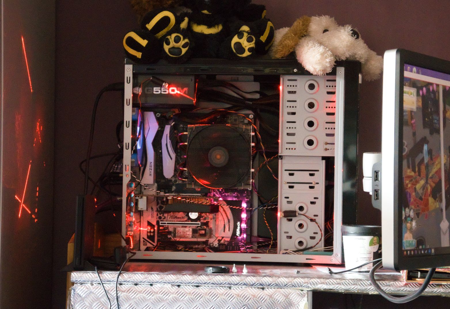
Anf finally, this is what it looks like working in the recipient's PC.