Amp4 - Subwoofer - Power Supply 2
This PSU could, theoretically, supply up to 8A for short periods, with the output sagging to ±14V at that current, but it will never be asked to supply anywhere near that much in the intended application and I would rather not push it to the limit in case I break something...
It's a capacitance multiplier. These work by amplifying an RC filter, rather than a voltage reference as a normal regulator does. It has certain benefits over a regulator, including lower power dissipation and smoother output ripple (high frequencies are attenuated more than low frequencies). It's improved compared to the usual design that is seen (emitter-follower buffered RC filter) with increased ripple rejection and/or smaller RC filter capacitor due to high input impedance, and lower dropout voltage due to use of pass transistors of opposite polarity to normal (limited only by RDS(on) multiplied by output current for MOSFETs, or VCE(sat) for BJTs). The cost is increased complexity, with six transistors used per rail.
Schematic
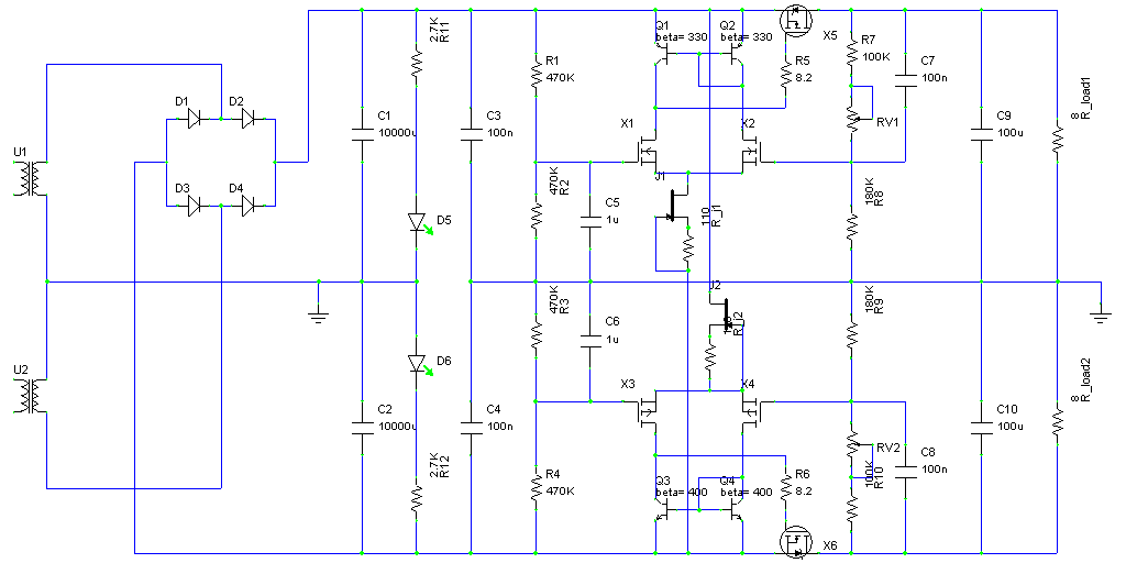
It consists of an RC filter (R1/C5 and R4/C6), then a differential amplifier (X1/X2 and X3/X4) which drives the pass transistor (X5 and X6). It is necessary to use feedback due to high output impedance of the pass transistors. Feedback is variable (via the 100kΩ RV1 and RV2) to allow adjustment of dropout voltage, which should be set so that it is always above the minimum possible (RDS(on) * Iout). MOSFETs have been used for the differential amp to give the highest possible input impedance, which allows the RC filter capacitor to be small enough to be a film type instead of electrolytic. JFETs are used as current sources (note that the resistors between their gates/sources can be omitted if the JFETs are selected to have IDSS equal to the required current). The exact current is not critical, but too low and ripple rejection suffers, too high is a waste of power. I chose 5.3mA as a reasonable value.
The high output impedance of the pass transistors causes ripple rejection to exhibit a peak when plotted vs. frequency, and it varies with load. This is a potential source of instability, but doesn't seem to be a problem with this particular design, thankfully.
Differential stage MOSFETs are ZVN2106A and ZVP2106A. The exact type is not critical here and they don't need to be specially matched. The only benefit to matching them is reduced DC offset, which is of course meaningless for a DC power supply. The BJTs making up the current mirrors are BC546B and BC556B. Again, the exact type is not critical and they do not need to be matched at all. Pass transistors are IRF5305 and IRLZ34N, chosen for particularly low RDS(on). JFETs are 2SK246GR, but anything with suitable IDSS will do, or a constant current diode (which are JFETs really), or any sort of current source. Simple resistors could be used instead, but proper current sources ensure consistent performance at any input voltage.
It's a pretty flexible design, being capable of working with input voltages up to about ±40V before the voltage ratings of the chosen devices are reached. With higher rated devices there is no reason it couldn't be scaled to much higher voltages. Output current capability is independent of input voltage, as long as dropout voltage is kept to a minimum.
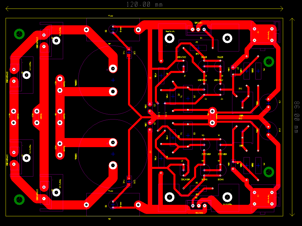
PCB layout
Very similar layout to PSU1: rectifiers and reservoir capacitors all onboard, two separate ground connections and LEDs under the fuse holders.
Building and testing
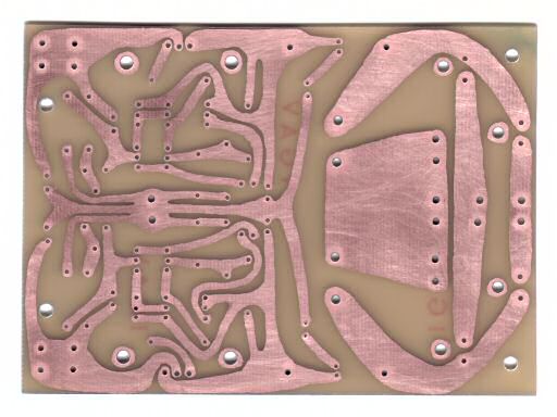
Next up a photo of the PCB after etching and cleaning. Since I hand-draw all my PCBs I can give everything a nice curved look (well it is called PCB artwork for a reason!):
A photo of it all assembled:
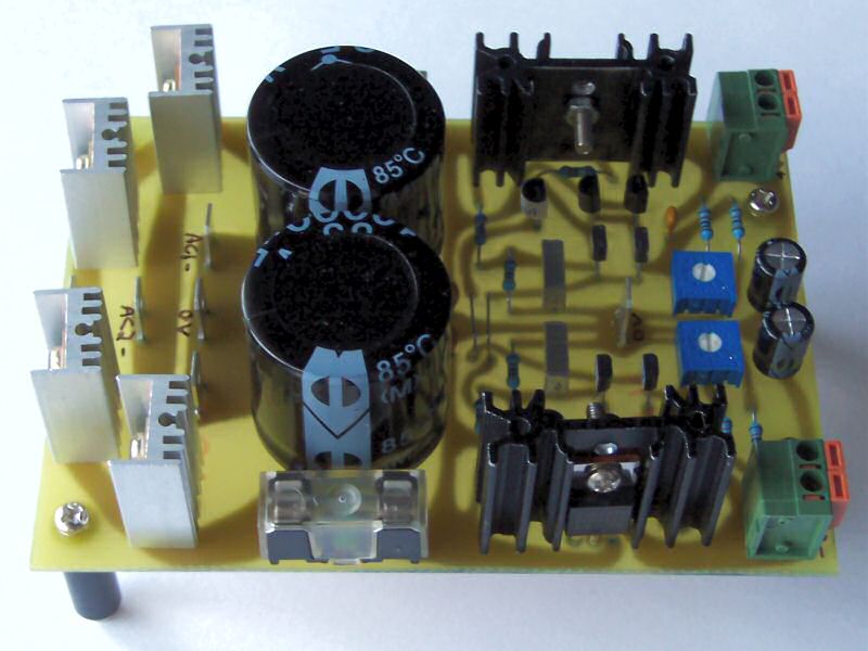
Yeah, the heatsinks on the diodes are overkill, but I recently pulled them off an old motherboard and wanted something to use them on. In fact the whole thing is overkill for the amount of power it has to supply to the amp (and the output stage doesn't even really need a regulated supply at all, since source-followers have inherently high PSRR), but a little over-engineering does no harm, and I'll take any excuse to make more stuff I enjoy :)
Measured performance looks pretty much identical to the simulations, with just a few mV of ripple at full output current. The waveform is rounded rather than the sawtooth shape given by a normal regulated supply (and unregulated supplies too). Ripple could be reduced to arbitrarily low levels by increasing the value of C5/C6, but that increases the time it takes for the voltage to ramp up to full when first turned on. That might be a good thing in some applications, but too low a voltage here when the input stage PSU is fully on could cause some distress to the amp, so best avoided here.