Solar Supercapacitor Charger
From my experience building a few solar lights, I learnt that despite Wikipedia saying that "changes in irradiation levels have a negligible effect on the maximum power point voltage", there is a significant difference in voltage between a solar panel's maximum power point (MPP) on a bright summer day and on a cloudy day in winter. To achieve both requires maximum power point tracking (MPPT). To learn more about how that works, I took the type of DC-DC converter I have previously used to charge a supercapacitor and added MPPT to it. I also wanted to use multiple supercapacitors in series instead of only one, both to store more energy and to provide a higher, more usable voltage. I already had a nominally 12V 5W solar panel to use.
Circuit
I played around with a bunch of different ideas to try to find something that would be both simple to understand and implement, eventually deciding on the "open voltage" method, which involves measuring the open-circuit voltage (VOC) of the panel, then assuming that the maximum power point voltage (VMPP) is a fixed fraction of that - about 0.8x for the panel I used. To actually track the MPP requires performing that measurement repeatedly as conditions change. For this I chose a microcontroller, the PIC12F1571, which has an ADC to perform the measurement, a DAC to output the appropriate reference voltage according to the measured voltage, and doesn't use very much power

The operation of the circuit is straightforward: The solar panel charges the reservoir capacitor C1, causing the voltage across it to increase. The comparator U2 compares that voltage with the reference voltage, turning on the MOSFET Q1 when it exceeds the reference voltage. This transfers charge from C1 through L1 to the load, reducing the voltage across C1. When that voltage drops back below the reference voltage, the comparator turns Q1 back off, and the cycle starts again.
The microcontroller U1 sets the reference voltage. To know what that voltage should be, every 2 seconds it outputs high to U2's SHDN pin, turning it off so that C1 can charge up to the full open-circuit voltage of the solar panel. Once enough time has passed for C1 to be fully charged, the microcontroller measures the voltage, sets the reference voltage, and turns the comparator back on. The calculation that VMPP = 0.8 x VOC is actually performed by the voltage divider consisting of R2 and R3, with R2 being 0.8 of the resistance of R2+R3. This is both faster and more accurate than using the PIC to do it.
The microcontroller also measures the output voltage via R9/R10, so it can stop charging the supercapacitors when they are full. It only checks this once every 2 seconds, at the same time it measures VOC, so the output voltage can overshoot, but that's fine as it will not overshoot very much in only 2s.
Finding a suitable comparator for U2 was difficult. It has to have a push-pull output so it can turn Q1 on and off quickly, use as little power as possible, and withstand the maximum voltage from the solar panel, which can be as high as 22V when it's sunny. The only one I could find is the TLV1805, which is quite new and wasn't available to buy anywhere when I started this project last year, so I had to wait a while before finishing.
There are quite a few other things to note:
- R5 pulls up the comparator's SHDN pin to ensure that it defaults to being shut down while the microcontroller starts up, or if the voltage is too low for it to work at all.
- R8 pulls up the gate of Q1 to keep it turned off while the comparator is shut down. R8 has to be much smaller than R6, as the two effectively form a voltage divider during this time, preventing Q1's gate voltage from being pulled all the way to 0.
- Although the comparator has some hysteresis built in, it's not sufficient to keep it stable in this circuit, so R4, R6 and C6 add some more.
- It looks like U1 and U2 have no local decoupling capacitors. Actually, the PCB is laid out such that they can share C2 and C3 with the voltage regulator U3.
- The ADC on the PIC can't read a voltage fast if its from a high impedance source like the voltage divider R9/R10. C5 reduces that impedance, allowing the ADC to work at normal speed.
- There must be a diode in series with the solar panel to prevent it from draining current from the load when its dark. This isn't shown on the schematic because the panel I'm using has one built in.
- D2 should to be of a type with low Vf, as it carries a few amps of peak current.
PCB

All the high-current tracks are at the top of the board, to keep loop-area small. There's plenty of copper around Q1, for heatsinking, although it dissipates very little power in use. D2 is at the edge of the board so it can get as much airflow as possible, as it does need to dissipate a bit of heat.
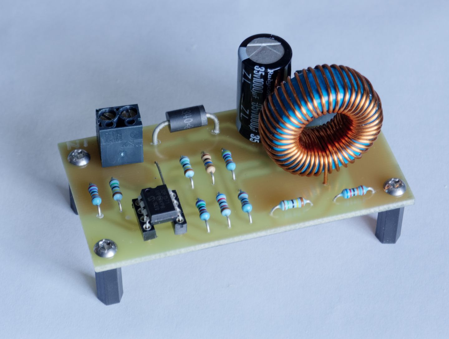
That's a big inductor! Inductors of that size tend to rather expensive if bought of-the-shelf, so I wound it myself on a T38 ferrite core. I experimented with different values for C1/L1, and 1µF/22mH yielded about the best efficiency. I'm sure a physically smaller inductor would have been fine too, if I wanted to spend the time winding a larger number of turns on a smaller core.
Firmware
Here's the firmware that runs on the microcontroller. It's very simple, so it fits in one file:
/*
 * MPPT for a solar panel. Reads the panel's Voc every 2 seconds, and outputs it on the DAC for a comparator to use as reference.
 */

// CONFIG1
#pragma config FOSC = INTOSC    //  (INTOSC oscillator; I/O function on CLKIN pin)
#pragma config WDTE = ON        // Watchdog Timer Enable (WDT enabled)
#pragma config PWRTE = ON       // Power-up Timer Enable (PWRT enabled)
#pragma config MCLRE = OFF      // MCLR Pin Function Select (MCLR/VPP pin function is digital input)
#pragma config CP = OFF         // Flash Program Memory Code Protection (Program memory code protection is disabled)
#pragma config BOREN = OFF      // Brown-out Reset Enable (Brown-out Reset disabled)
#pragma config CLKOUTEN = OFF   // Clock Out Enable (CLKOUT function is disabled. I/O or oscillator function on the CLKOUT pin)

// CONFIG2
#pragma config WRT = OFF        // Flash Memory Self-Write Protection (Write protection off)
#pragma config PLLEN = OFF      // PLL Enable (4x PLL disabled)
#pragma config STVREN = ON      // Stack Overflow/Underflow Reset Enable (Stack Overflow or Underflow will cause a Reset)
#pragma config BORV = LO        // Brown-out Reset Voltage Selection (Brown-out Reset Voltage (Vbor), low trip point selected.)
#pragma config LPBOREN = ON     // Low Power Brown-out Reset enable bit (LPBOR is enabled)
#pragma config LVP = OFF        // Low-Voltage Programming Enable (High-voltage on MCLR/VPP must be used for programming)

#include <stdlib.h>
#include <xc.h>

//Clock frequency. Used by delay loops etc.
#define _XTAL_FREQ 16000000

#define INPUT_ADC_CHANNEL 1 // For measuring solar panel Voc.
#define MIN_INPUT 100 // What the ADC will measure if the panel voltage is at the minimum of 9V.
#define OUTPUT_ADC_CHANNEL 2 // For measuring output voltage.
#define MAX_OUTPUT 244 // What the ADC will measure when the output voltage reaches the maximum allowed 10.8V.

void init()
{
	OSCCONbits.IRCF = 0b1111; // 16MHz clock. A high clock allows the time spent awake to be minimized, reducing total energy use.
	WDTCONbits.WDTPS = 0b01011; // 2s watchdog timer.
	VREGCONbits.VREGPM = 1; // Low-power sleep.

	TRISAbits.TRISA0 = 0; // RA0 as analogue output (DAC1OUT)
	ANSELAbits.ANSA0 = 1;
	WPUAbits.WPUA0 = 0;

	TRISAbits.TRISA1 = 1; // RA1 as analogue input (AN1)
	ANSELAbits.ANSA1 = 1;
	WPUAbits.WPUA1 = 0;

	TRISAbits.TRISA2 = 1; // RA2 as analogue input (AN2)
	ANSELAbits.ANSA2 = 1;
	WPUAbits.WPUA2 = 0;

	// RA<3:4> as inputs with weak pull-ups, just to stop them floating.
	TRISAbits.TRISA3 = 1;
	TRISAbits.TRISA4 = 1;
	WPUAbits.WPUA3 = 1;
	WPUAbits.WPUA4 = 1;

	LATAbits.LATA5 = 1; // Set to 1 initially to ensure converter starts in shutdown.
	TRISAbits.TRISA5 = 0; // RA5 as digital output.
	WPUAbits.WPUA5 = 0; // This is pulled up externally.

	OPTION_REGbits.nWPUEN = 0; // Globally enable weak pull-ups.

	ADCON1bits.ADFM = 0; // Left justified.
	ADCON1bits.ADCS = 0b101; // Set ADC clock to Fosc/16 for a 1µs Tad.
	ADCON1bits.ADPREF = 0b00; // Set ref to Vdd.

	DACCON0bits.DACEN = 1; // Enable DAC
	DACCON0bits.DACOE = 1; // Send DAC output to DAC1OUT (RA0).
	DACCON0bits.DACPSS = 0b00; // Set positive source to Vdd.
}

unsigned char ReadADC()
{
	for(GO_nDONE = 1; GO_nDONE;){} //Start conversion and wait until it's done.

	return ADRESH; // Ignore lower byte - 8bits of resolution is enough.
}

void DisconnectPanel()
{
	// Disabling the converter is as good as actually disconnecting the panel.
	LATAbits.LATA5 = 1;
}

void ConnectPanel()
{
	LATAbits.LATA5 = 0;
}

void WaitForCapacitorCharge()
{
	// Even though this is a short wait, it's important to SLEEP rather than just spinning, to avoid consuming power that could be used to charge the capacitor quicker.
	WDTCONbits.WDTPS = 0b00100; // 16ms watchdog timer. This should be enough for the capacitor to charge to Voc, even when there is very little current available from the panel.
	SLEEP(); // The watchdog timer will wake from sleep.
}

void WaitForNextRefresh()
{
	WDTCONbits.WDTPS = 0b01011; // 2s watchdog timer. This is a compromise between quick response, and energy missed while the panel is disconnected.
	SLEEP(); // The watchdog timer will wake from sleep.
}

void EnableADC(const unsigned char channel)
{
	ADCON0bits.CHS = channel;
	ADCON0bits.ADON = 1;
}

void DisableADC()
{
	ADCON0bits.ADON = 0;
}

void SetReferenceVoltage(const unsigned char Voc)
{
	unsigned char output;

	// Limit the minimum MPP. If it's too low, there won't be enough power for things to work properly.
	if (Voc < MIN_INPUT)
	{
		output = MIN_INPUT;
	}
	else
	{
		output = Voc;
	}
	output >>= 3; // DAC is only 5 bit.

	DACCON1 = output;
}

int main(void)
{
	unsigned char Vo;
	unsigned char Voc;

	init();

	while (1)
	{
		SetReferenceVoltage(255); // Set ref to max so the comparator turns the MOSFET off before it is disabled.

		// Measure output voltage first.
		EnableADC(OUTPUT_ADC_CHANNEL);
		__delay_us(5); //Wait for acquisition time.
		Vo = ReadADC();

		DisconnectPanel(); // While the panel is disconnected, the reservoir capacitor can charge up to Voc.

		EnableADC(INPUT_ADC_CHANNEL); // Enable ADC while reservoir capacitor is charging so it has plenty of time for acquisition, which is slow due to the large resistance at its input.
		WaitForCapacitorCharge();

		// Now measure Voc.
		Voc = ReadADC();
		SetReferenceVoltage(Voc);

		if (Vo < MAX_OUTPUT // Stop charging at the preset output voltage.
			&& Voc > (Vo >> 1)) // Energy can't be transferred to the output if the input voltage is less than the output voltage. Vo is scaled by about 2 compared to Voc, hence the right shift.
		{
			ConnectPanel();
		}

		DisableADC(); // Disable ADC to conserve power. Not strictly necessary, since it is disabled during sleep anyway.
		WaitForNextRefresh();
	}

	return EXIT_FAILURE;
}
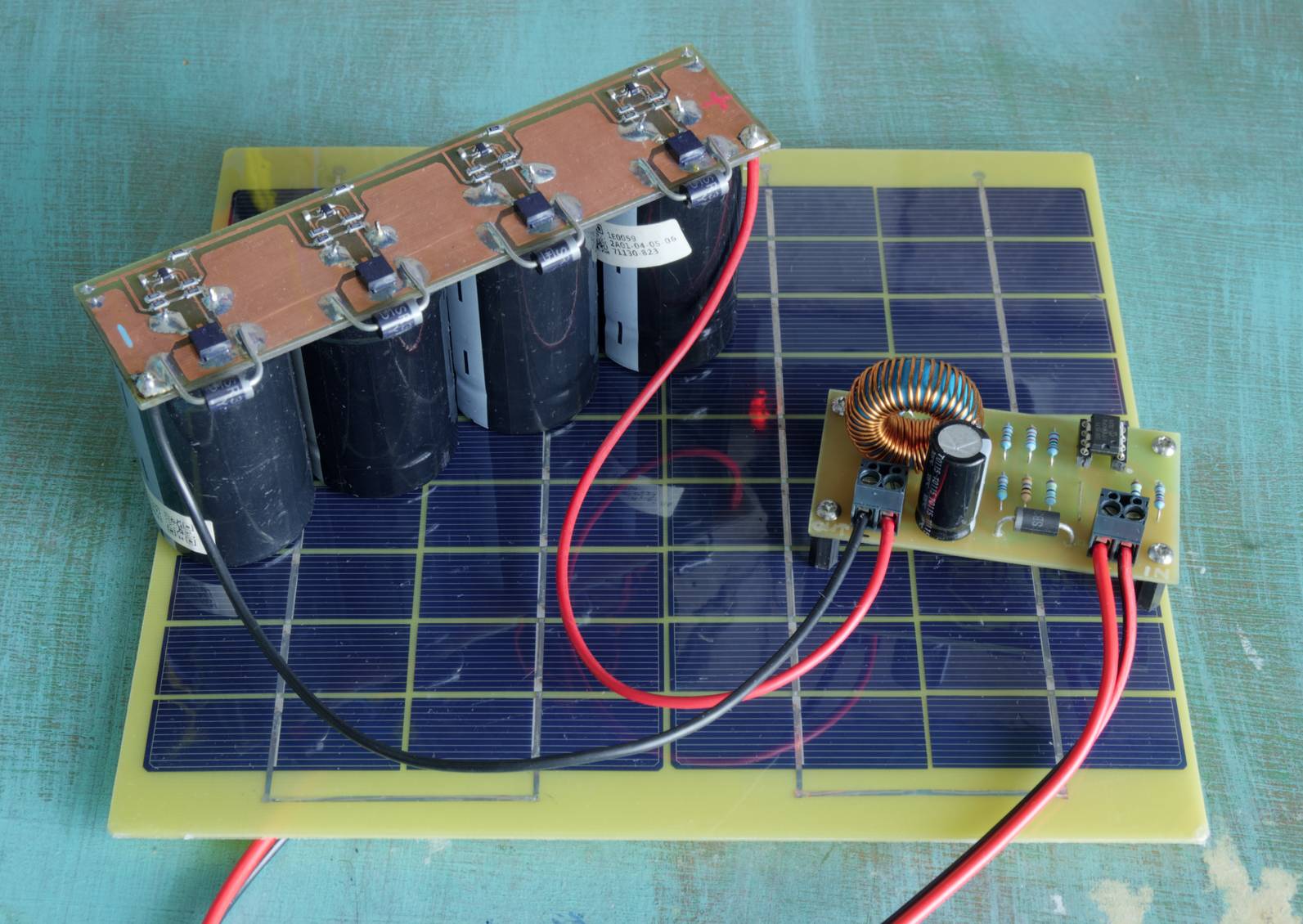
Measurements
For testing, I connected the DC-DC converter, solar panel, and supercapacitor bank together and placed them first under an artificial light, so I could control the amount of light, and then under what passes for "sunlight" at this time of year.
It draws only 40µA of quiescent current, allowing it to operate even when the solar panel is producing as little as 180µA, though it would take forever to finish charging at that rate. And now a screenshot of what it looks like on an oscilloscope, just as the microcontroller takes a sample:
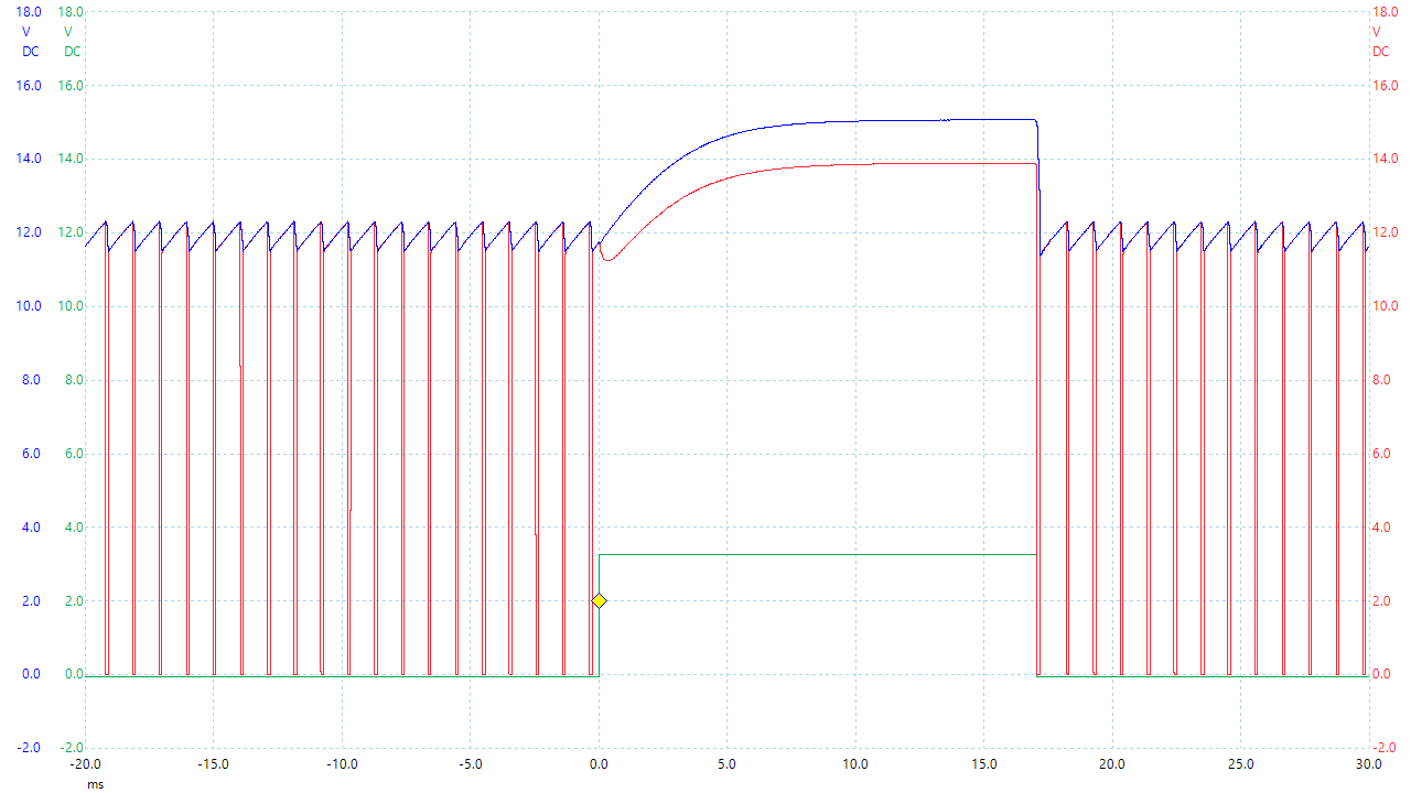
At the start of the trace the comparator is doing its thing - the panel voltage rises, Q1 switches on, the panel voltage falls, Q2 switches off. Then the microcontroller sets SHDN high, and it all stops. The panel voltage rises until it eventually reaches VOC. During this time you may notice that Q1's gate voltage increases too (since it's a P-channel high-side switch, its gate voltage is the difference between the blue and red traces, not the difference between the red trace and ground). This is because with U2 shut down, its output goes into a high-impedance state, and the gate voltage becomes defined by R8/R6 as a voltage divider. That's good enough as long as it's not high enough to turn Q1 on. Then after the microcontroller has waited for 16ms, it takes a sample of the panel voltage and turns U2 back on again.
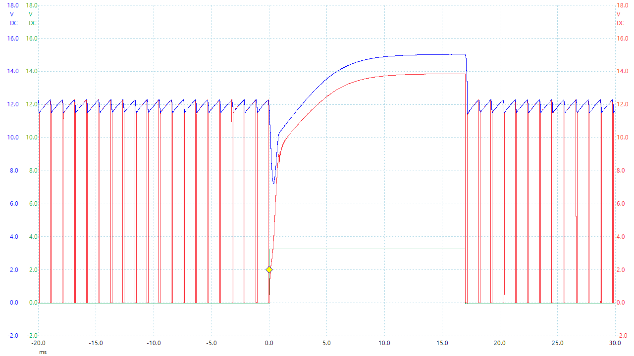
That trace shows something I hadn't originally anticipated: If the microcontroller shuts down U2 while Q1 is on, it can only be switched off by R8 pulling up, which it can only do slowly because of its high value. If I wanted to, that could be fixed I fixed that in the firmware by setting the reference voltage to its maximum possible value then waiting a short time so that the comparator turns Q1 off before being shut down itself.
Measuring the efficiency is next, in sunlight. As it's currently winter and not sunny, the solar panel generates somewhat less than its 5W rating.
| VOC | 18.2V |
|---|---|
| ISC | 6.1mA |
| Vin | 13.6V |
| Iin | 5.55mA |
| Pin | 75.5mW |
| Vout | 4.45V |
| Iout | 14.6mA |
| Pout | 65.0mW |
| Efficiency | 86% |
86% efficiency is acceptable. It will likely be more efficient when there is actually some sun, but I'll have to wait until summer to test that. Note that the Vin of 13.6V is less than 0.8 x VOC. That's partly because the microcontroller only has a 5-bit DAC, so there are quite large steps in the reference voltage it can produce, and partly because the quiescent current drawn by the circuit prevents the microcontroller from reading the true VOC when the panel isn't producing much current like this.
This is a good demonstration of why MPPT is needed - the panel's specifications say VMPP is 17.2V, which is a lot higher than it was for the above measurements. If the circuit used a fixed voltage of 17.2V, then it would be fine in bright sun, but in the conditions above it would only be able to extract something like 40mW even at 100% efficiency. It's also worth comparing this to a direct connection between the panel and supercapacitor bank, which would yield about 27mW.
I'm not sure quite what I'm going to use this for yet. Maybe a big solar light.